
The true depth of cut at any position в is the difference in workpiece radius at that position and the value of radius at the same position one revolution earlier.
ae (в) = r (в) — r (в — 2n) (19.54)
Similarly, the set depth of cut is the difference between the set reduction in radius at a particular position and the true reduction in radius one revolution earlier.
А(в) = Я(в) — r (в — 2п) (19.55)
Substituting Equation 19.45 into Equation 19.55 and from Equation 19.47 and Equation 19.54, the Basic Equation results:
r (в) = K ■ [X (в) + K1 • r (в — a) — K2 • r (в-к + р) — r (в — 2п)] + г(в — 2n) (19.56)
This basic equation with some restrictions may be used to simulate a wide variety of conditions that occur in centerless grinding.
19.11.6 Simulation
Simulation is a technique that became popular with the advent of computers. In 1961, it was realized that simulating the process on the Manchester University Mercury computer would make it possible to compare experimental workpiece shapes with predicted shapes and hence discover many important aspects of how the process works [Rowe and Barash 1964]. The technique is reviewed here for its usefulness in explaining the rounding process.
The workpiece circumference is divided into small steps with respect to a radial line of origin. Typically, steps of 1° were sufficient. Initial values of workpiece radius errors were stored for positions around the workpiece. These values represent a set from r (-360) to r (-1) when в = 0°. These values, along with any suitable increments for the infeed motion, can be fed into Equation 19.56. The angle theta is increased one step at a time and values calculated for r(0). These values are stored and represent the developing profile of the workpiece.
It is thus possible to examine the effects of different infeed functions including the importance of the dwell period. Various initial shapes can be investigated as these are a main source of variability between final shapes after grinding. It is even possible to consider the effects of machine vibrations on roundness.
It quickly becomes apparent that restrictions need to be applied to prevent radius increasing. This is the metal replacement restriction and is applied by incorporating a conditional statement. This and other restrictions required are
• Metal Replacement Restriction. The value of r (в) is compared with the value of r (в — 2n) and replaced by the previous value whenever metal replacement is implied.
• Grinding Wheel Interference. With high frequencies and large radius variations from step to step, it is not possible for the shape to be accommodated. This is because the radius of the grinding wheel will interfere with workpiece positions adjacent to the point of contact. This is illustrated in Figure 19.36.
Grinding wheel interference has a practical benefit in grinding in that it limits the development of higher frequency vibrations and has the effect of smoothing the profile. The restriction is applied at nearby positions by calculating the clearance,
and the interference,
![]()
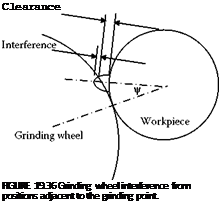 |
I^ = r (в) + W¥- r (в — 2n)
 |
Modifications only need to be made for positive interference. An amount of material is removed at the adjacent position equal to the interference, I¥, multiplied by the machining-elasticity parameter K.
• Control Wheel Interference and Workrest Interference Restrictions. Interference at the control wheel and workrest are calculated similarly to the previous example. The largest interference is found and subtracted from the usual term at each contact.
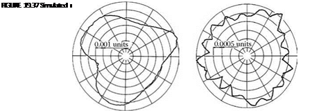
Figure 19.37 shows typical simulation results for a uniform infeed. In both cases, errors due to the infeed are less than 1% of the infeed per revolution after 45 revolutions.
With small values of в, 3 and 5 lobe shapes predominate. Constant diameter shapes can roll between parallel tangents in the same way as a pure cylinder. With zero tangent angles, there is, therefore, no rounding action of odd lobe shapes. With в = 10° and у = 20°, the rounding geometry is unstable for 16 lobes. The resulting roundness errors are small because there was very little excitation of the instability in the simulation. In practice, roundness errors are very much affected by level of excitation.
Poor roundness will result if the machine resonates at a frequency of instability. The workspeed should, therefore, be set to avoid excitation of an unstable frequency. For this geometry, and a resonant frequency of 72 Hz, workpiece speeds should be avoided in the region of
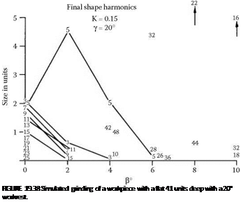
Initial shape errors vary greatly in practice depending on the previous machining process. Effects of initial shape on the final ground shape were investigated using a controlled error. A small flat was machined along the length of the workpiece as described in Section 19.11.7. The workpiece with a flat has a similar effect in grinding to an impulsive force and excites a wide range of frequencies each time the flat passes a contact point.
A series of simulations was performed for a workpiece with a flat. Amplitudes of the workpiece shape harmonics determined by Fourier analysis are illustrated in Figure 19.38. It is seen that 5 lobes predominate at a low tangent angle and even-order lobing at larger tangent angles. At 10°, 16 waves are strongly evident. At 8°, 22 waves appear and also 44 waves. As the tangent angle is increased, the number of even order waves for the predominant harmonic reduces. That is 32 waves, 22 waves, and then 16 waves. Lower numbers of waves tend to present a greater problem than higher numbers of waves. This is because higher frequencies are more likely to be filtered by interference with the grinding wheel, control wheel, and workrest. Higher frequencies may also be smoothed by workpiece inertia.
 |
Figures 19.39 shows simulation results for a 30° workrest. Despite assuming a more compliant system, K = 0.08, the rounding action was much stronger than in the previous case. The buildup of even-order waviness was less pronounced with the 30° workrest than with a 20° workrest.