
This discussion deals only with the case of plunge feed, although the analysis has significance also for through-feed.
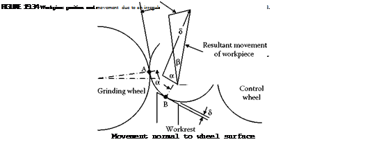
Figure 19.34 defines position on the workpiece. A line of origin OX can be considered to rotate with the workpiece. Positions on the workpiece surface are defined by the angle from the line of origin. The position A is defined by the angle в so that as the workpiece rotates the angle в increases. When в = 0 or в = 2nn the line OX is coincident with OA.
In a similar way, Point B at в-a defines the point of contact with the workrest. Point C at в-п+в defines the point of contact with the control wheel.
If an irregularity on the workpiece arrives at the workrest as shown in Figure 19.34, the center of the workpiece will be displaced. Assuming the workpiece movement is constrained to slide along the tangent of workpiece contact with the control wheel, the movement can be calculated. The workpiece will be pushed away from the workrest at Point B. As a consequence of the movement the workpiece will move away from the grinding wheel at Point A. In this way, an irregularity at Point B gives rise to a further irregularity at Point A. The irregularity can be considered as a local shape error.
 |
The error at Point A due to an irregularity of magnitude 81 on the workpiece at Point B is
+ sin в 8 sin(a+e) 1
The error at Point A, due to an irregularity of magnitude 82 on the workpiece at Point C, is
— sina 8
sin(a + e) 2
A reduction in radius from an initial reference circle is considered as an error. If the machine and grinding wheels were absolutely rigid, the apparent reduction in radius R(6) may be calculated in terms of the infeed movement X(в) considered in a direction OA and the 81 and 82 errors. Defining 81 = — r(в-a) and 82 = -т(в-п + в),
R(e) = X(в) + Kt ■ r(в-a)-K2 • r(в-п + в) (19.45)
where
The machine and grinding wheels are not rigid and, therefore, Equation 19.45 is termed the apparent reduction in radius. The true reduction in radius depends on the deflection of the system.
The true reduction in radius at the grinding wheel contact point A is r(&) = R(&) — x(9), where x(&) is the deflection at the grinding point. Equation 19.45, therefore, becomes
r(0) = X(в)- x(0) + Kx ■ r(Q-a)-K2 ■ r(в-л + р) (19.46)
For the case where в = 10° and a = 55°, the value of K1 is approximately equal to 0.2 and the value of K2 is approximately equal to 0.9. Clearly, an irregularity arriving at the control wheel contact point has a stronger effect than an irregularity arriving at the workrest contact point.