
Rounding geometry was introduced in Section 19.2.5. A question of interest is whether centerless grinding is ultimately capable of the highest standards of roundness. In recent years, it has become apparent that achievable standards of roundness are approaching the limits of available measuring machines [Hashimoto et al. 1983].
The question of ultimate roundness is less likely to be posed in this way for most other processes such as cylindrical grinding between centers where the potential achievement of high accuracy tends to be taken for granted and is often assumed to depend only on practical considerations. This may be partly justified although high standards of roundness are often more easily obtained by centerless grinding rather than by grinding between centers where center holes need to be lapped to minimize transmission of shape errors to the cylindrical surface being produced.
19.11.1 Avoiding Convenient Waviness
Three — and five-lobe shapes may sometimes persist after centerless grinding. Fortunately, three — and five — lobe shapes may easily be removed by grinding at the correct height above center. Odd order lobing tends to persist with a zero or small value of the tangent angle. Odd order lobing is a constant diameter shape sometimes known as a Gleichdicke shape. A constant diameter Gleichdicke shape can exist and rotate between parallel tangents as provided by the grinding wheel and the control wheel at zero center — height. Gleichdicke deviations from circularity remain undetected by diameter measurement.
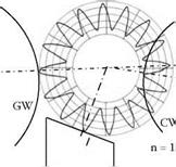
An example of a five-lobe shape is shown in Figure 19.33. The large roundness error resulted from grinding a workpiece at a zero tangent angle. The grinding wheel, control wheel, and workrest shapes are superposed on the greatly magnified deviations from circularity of the workpiece. Normally, it is impossible to see roundness errors with the naked eye.
The angle of the workrest has no effect on rounding at в = 0°. This is because any small movements toward or away from the workrest simply cause the workpiece to move vertically up and down the vertical tangent at the control wheel contact point. As the workpiece rotates, the odd-lobe shape is accommodated in the constant distance between the grinding wheel and the control wheel.
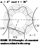
Even-lobe shapes are more likely to occur at large values of tangent angle. This situation is also illustrated in Figure 19.33. In the example for в = 10° and y = 20°, 16 waves are produced,
 в = 10° and y = 20°
 WR
WR
that is, n = 16. An explanation for the susceptibility of this setup to 16 waves can be found by considering the angular pitch of the waviness, p = 360/n. Each wave in this example is separated by a pitch, p = 360/16 = 22.5°. Sixteen waves fit neatly so that the waviness is almost unaffected by movement against the workrest. This can be demonstrated as follows.
For в = 10° and у = 20°, the value a ~ 66° so that
~ 2.93 ~ 3 is equal to an integer
p
Due to the integer relationship, 16 waves are practically unaffected by the contact with the workrest. A peak in contact with the workrest coincides with a peak at the grinding contact. Corrective action due to contact with a workrest is explained in more detail in Section 19.11.2.
Sixteen waves are also unaffected by contact with the control wheel since
180—в = 7.55 ~ 7.5 is equal to a half-integer
p
The implication is that when the crest of a wave contacts the control wheel, the trough of another wave contacts the grinding wheel and there is no corrective action.
It might be expected that n = 18 with p = 20° would also be a problem for в = 10°, since 180 — в = 8.5 • p. This provides exactly the half-integer relationship required for insensitivity to the control wheel contact. However, in this case, a~ 3.3 • p, which is well removed from an integer value and is closer to being a half-integer value. The workrest, therefore, has a stronger corrective action on 18 waves than in the previous example for 16 waves.