The control wheel spindle bearings were the most compliant element in the force loop compliances shown in Figure 19.18. The plain hydrodynamic bearings of the control wheel spindle are shown as Element F1. Plain hydrodynamic bearings are reliable over a long period, but at low speeds they exhibit low and variable compliance The compliance becomes very high under light loading as when sparking out. This is a serious disadvantage for consistency of grinding. Hydrodynamic bearings are much better at high speeds as when applied in grinding wheel bearings. High-precision rolling elements are better than plain bearings for low speeds, but need to be replaced regularly due to wear. Hydrostatic bearings give improved performance over the speed range having high stiffness, high accuracy, and low wear properties. The disadvantage of hydrostatic bearings is higher cost.
Hydrostatic bearings were substituted for the hydrodynamic control wheel bearings of the conventional machine. The hydrostatic bearings were provided with diaphragm control to improve

the system stiffness, consistency, and rotational accuracy. The replacement bearings are shown as Element F2 in Figure 19.18. The grinding wheel bearings were also replaced by hydrostatic bearings giving marginally improved stiffness but much-improved rotational accuracy. The result was much better roundness accuracy of the grinding process. The replacement of the control wheel bearings gave much improved size-holding capability. It was possible to achieve a specified size tolerance within a shorter dwell period for spark-out.
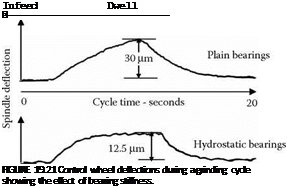
Figure 19.21 shows how bearing stiffness affects deflection of the control wheel in plunge grinding for a workpiece 25.4 mm diameter by 50 mm long. The maximum deflections are two and a half times larger with the plain bearings than with the hydrostatic bearings for the control wheel spindle.
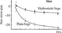
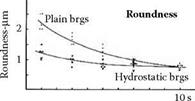
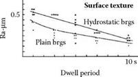
Greater deflections of the grinding system require a longer spark-out dwell to reduce the size roundness and surface texture variations. Controlled grinding experiments demonstrate this effect and the results are seen in Figure 19.22.
Size variations are much smaller with the stiff hydrostatic bearings than with the compliant plain bearings. Size variations are reduced to a negligible level in half the dwell period required by the compliant bearings.
Roundness errors also decrease during the dwell period. Stiff hydrostatic bearings reduce roundness errors faster. In later experiments, the grinding wheel bearings were replaced by hydrostatic bearings and the roundness errors were further reduced.
The results for surface texture may seem surprising. Surface roughness reduces during the dwell period as would be expected. However, surface roughness is greater for the stiffer hydrostatic bearings than for the compliant plain bearings. Experience with other machines confirms that stiff systems produce slightly higher surface roughness in grinding. On reflection, this would be expected since a stiffer system imposes greater variations in grain depth than a soft system. A stiff system can produce low roughness but the requirement for low roughness is a system where grain depths are small and uniform. This can be achieved with high-quality small-grain wheels and a low level of vibrations.
Overall stiffness of a system in relation to grinding forces is expressed by the machining — elasticity parameter K. The parameter K is the true depth of cut divided by set depth of cut and is explained mathematically in Section 19.11.4. Evaluating K for the hydrostatic bearing machine and the plain bearing machine gave the following results in controlled grinding experiments:
Plain bearing machine K = 0.23
Hydrostatic bearing machine K = 0.44
In summary, replacing compliant plain wheel bearings by stiff hydrostatic bearings almost doubled the effective system stiffness.
|
|
|
|
|
FIGURE 19.22 Workpiece accuracy with dwell period. Comparing stiff hydrostatic control wheel bearings with compliant hydrodynamic control wheel bearings. |


