A conventional machine layout constrains the workpiece within a U-section, whereas ideally the workpiece should be constrained within a closed-box layout. This point is illustrated in Figure 19.19. The U-section is inherently subject to deflections in the same manner as a tuning fork. Ideally, a machine should be constructed in a different way designed to resist deflections.
A highly accurate and very stiff research machine was designed and built to demonstrate this point. The layout is illustrated in Figure 19.19. The research machine allowed grinding results to be compared with results from a compliant conventional machine. The structural design was shaped by the following criteria:
• The line of measurement to be coincident with the line of separating force
• The neutral axis for bending to be coincident with the line of force
• The dressing point to be opposite the grinding point on the grinding wheel and opposite the control wheel contact point on the control wheel, that is, along the line of force
• The dressing cam plates to be on the same line of force
• Hydrostatic bearings to be employed for high stiffness and accuracy
• A highly accurate and highly damped feed drive to be provided by a wedge-shaped cam driven between hydrostatic bearings
• The same principles to apply in the plan view. The wheels to be supported symmetrically between the spindle bearings
The resulting wheel-workpiece stiffness was 3.5 x 10⁷ N/m, five times greater than the stiffness of the conventional machine. The resonant frequency was increased from 78 Hz to 500 Hz.
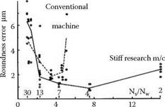
The stiff machine gave different grinding results from a conventional machine. Size control and roundness using a similar plunge grinding cycle were improved but the range of workspeeds over which accurate grinding could be achieved was greatly increased as shown in Figure 19.20.
|
Workspeed in rev/s Nw FIGURE 19.20 Effect of machine design on roundness accuracy and operating speed range. |