
A different problem can arise with heavy workpieces if there is insufficient control wheel friction to turn the workpiece on contact with the grinding wheel. Heavy workpieces are unlikely to suffer the problem of “spinning.” In fact, heavy workpieces are more likely to suffer the problem of failing to turn at all under the action of the grinding force. If the workpiece fails to turn, the grinding wheel can machine a groove on one side of the workpiece. This situation is potentially dangerous since as the size of the groove increases, the tangential grinding force also increases to the point where the workpiece suddenly starts to rotate, leading to an excessive depth of cut and exceptionally heavy forces on the grinding wheel. It is important that this situation is never allowed to arise since it could lead to wheel breakage. When setting up a grinding process, it is important to check that the workpieces readily rotate and stop the machine if rotation fails to occur.
For heavy workpieces, additional provision must be made to ensure workpiece rotation before contact with the grinding wheel. An additional pressure roll may be employed to push the workpiece
against the control wheel and this may be sufficient. For very large workpieces such as axle shaft housings, it will be necessary to provide an external driving device to grip and rotate the workpiece.
19.8.1 The Basic Machine Elements
Main elements of a centerless machine include:
• The machine base and table
• The grinding wheelhead, spindle bearings, and spindle drive
• The control wheelhead, spindle bearings, and spindle drive
• The infeed drive
• The grinding wheel dressing slide and drive
• The control wheel dressing slide and drive
• The workrest slide
• The fluid delivery and return system
The design of the machine must allow the machine
• To accurately position the workpieces in relation to the grinding wheel
• To drive the grinding wheel, control wheel, and workpieces at precise speeds
• To accurately dress the wheels
In this section, aspects of machine design are considered in relation to performance. Results from a conventional machine of the type shown in Figure 19.16 are compared with results from a stiff research machine having the layout illustrated in Figure 19.19. Further information is available in publications by Rowe [1974] and Rowe, Spraggett, and Gill [1987].
19.8.2 The Grinding Force Loop
|
Figure 19.16 shows the layout of a very basic centerless machine. In this example, the grinding wheelhead forms part of an integral table and fluid containment tray. There is provision of a slideway Control wheelhead
|
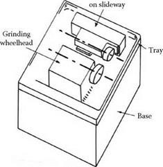
on the table to allow feed of the control wheelhead. No provision is shown to feed the grinding wheelhead nor is provision for angular adjustments to the wheelhead. These features are incorporated into many machines for ease of operation and setup.
Forces in the process cause deflections of the machine leading to the possibility of size inaccuracy and lack of straightness and roundness. Machine design affects both accuracy and production rate since a machine that is more compliant usually has to be operated more slowly to achieve the same accuracy. Often a more compliant machine is incapable of producing the same accuracy as a stiffer and better-designed machine. It is demonstrated below that a stiffer machine reaches the size specification faster than a compliant machine.
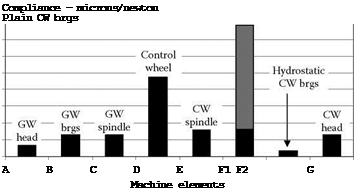
The forces in the process are reacted through a chain of machine elements. The overall compliance of the machine depends on the buildup of compliance through the elements in the force loop. The main elements of the loop for the grinding force are shown in Figure 19.17. The compliances of various elements are shown in Figure 19.18. The elasticity of the grinding wheel is not shown, although this is of a similar order of magnitude to the compliance of the control wheel but rather stiffer [Rowe 1974]. Other loops may be constructed for the dressing forces.
 90 80 70 60 50 40 30 20 10 0
|
|
|
|
|
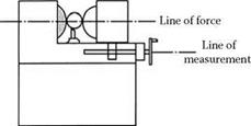
FIGURE 19.19
Each of the elements in the loop plays a critical role in resisting deflections. In this example, the low-speed plain control wheel bearings are a source of variability and low stiffness under finishing conditions. In addition, the workpiece is also featured in the force loop. If the workpiece is a thin-walled cylinder, the stiffness of the force loop will be greatly reduced.