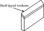
The support surface of a workrest should be harder than the workpiece. The workrest also has to be tough and capable of withstanding the knocks encountered on the factory floor. The wear-resistant surface of the workrest is selected according to the types of work material ground. For steels, tungsten carbide inserts provide a suitable surface. A typical tipped workrest is illustrated in Figure 19.14.
 ..Workrest angle у
Г
Formed workpieces require the workrest to be shaped to support the workpiece at more than one position along its length. For example, if the workpiece is stepped, the workrest must also be stepped. The step height on the workrest should correspond to the step height on the workpiece.
The top surface of the workrest is almost invariably angled as shown. The workrest angle, y, may lie between 0 and 45°. For most work, the angle chosen is 30°. The angle 30° is generally found to give a strong rounding action. A workrest angle of 0°is to be avoided since no rounding action is achieved. The effect of workrest angle is introduced in Section 19.2.5 on rounding geometry.
It is important that the workrest is set horizontal and parallel to the grinding-wheel surface to avoid problems of taper errors on the workpiece and forward ejection of workpieces from the machine.
For light workpieces, contact with the grinding wheel is sufficient to provide the driving torque to ensure workpiece rotation. A freshly dressed rubber control wheel gives good friction and prevents workpieces from spinning out of control. With sufficient friction, the workrest and the control wheel both resist rotation of the workpiece against the driving torque provided by the grinding wheel. Under these conditions, the workpiece follows the speed of the control wheel.
19.7.1 Spinning Out of Control
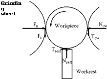
With insufficient friction, the workpiece speeds up. This causes the friction coefficient between the workpiece and the regulating wheel to further reduce. The loss of friction causes the workpiece to spin out of control. To avoid this situation, the surfaces of the control wheel and workrest must be clean. Also, the control wheel surface must provide adequate friction. The condition for spinning can be illustrated for the condition illustrated in Figure 19.15 for zero work-height above center.
The grinding wheel exerts a normal force, Fn, and a tangential force, Ft. The force ratio may be expressed as a grinding-wheel friction coefficient, Fgw. The normal force, Nrest, exerted by the workrest approximately balances Ft. The frictional force on the workrest is given by the coefficient of friction, ^rest, for the two materials under the sliding conditions. Forces on the workpiece balance in the horizontal direction, in the vertical direction, and for rotation. These conditions lead to
F = N + T…. Horizontal forces (19.23)
n cw wr v 7
F = U ■ F = N — T…. Vertical forces (19.24)
t ~ gw n wr cw v 7
 |
|
Twr = Vwr ■ Nwr = F — Tcw.. Rotational forces (19.25)
