
The axis of the control wheel is inclined at an angle, Ф, sufficient to provide traction in the axial direction. A small angle is employed for plunge grinding and a larger angle for through grinding as explained previously. This means the axis of the control wheel is not parallel with the axis of the workpiece. If the control wheel is dressed as a straight cylinder, the angle means there is point contact between the workpiece and the control wheel instead of line contact. Clearly, point contact will not ensure correct positioning of the workpiece parallel to the grinding wheel axis.
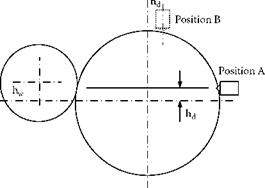
Line contact can be ensured between the control wheel and workpiece by dressing the control wheel along the required line of contact. A similar result can be achieved by dressing the control wheel parallel to the required line of contact but directly opposite in the same horizontal plane. This is illustrated in Figure 19.12.
The dressing tool must be set at a height, hd, that is related to the work center-height, hw. The dressing height is
d
hd = h———————— ^ (19.21)
d w d + d
c w
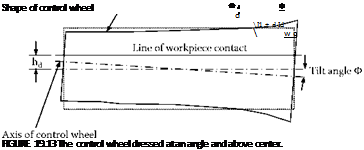
The control wheel is no longer a true cylinder when tilted at an angle, Ф, and trued at a height, hd. It becomes an hyperboloid. The shape of the control wheel is shown schematically in Figure 19.13. The line of contact corresponds to the line of truing. Truing defines the diameter at each section of the control wheel. As the tool traverses across the control wheel, the height of the tool becomes higher relative to the center of the wheel. This increases the diameter of the wheel. The control wheel becomes larger at the low end of the wheel than at the other and satisfies the requirement that the workpiece is supported on a parallel line of contact with the grinding wheel.
|
|
 |
|
If the dressing is carried out at Position B in Figure 19.12, it is necessary to make additional adjustments for the angles involved. The dressing slide must be rotated relative to the plane of the line of contact by an angle approximately equal to the angle of tilt. The required rotation is made in a plane parallel to the tangent to the control wheel at the point of contact with the dressing tool. An adjustment is made to the angle for larger diameter workpieces. The dressing angle for Position B as given by Jessup, in the book by King and Hahn [1986], is
Hashimoto, Kanai, and Miyashita [1983] demonstrated a major source of errors in centerless grinding is due to runout of the control wheel. To prove this point, the workrest assembly was removed to allow the control wheel to be advanced up to the grinding wheel. By this means, the control wheel was dressed by the grinding wheel with much greater precision than possible by the normal method of dressing.
It was found that roundness errors were reduced from 1.7 to 0.2 pm with high-precision dressing and surface roughness was reduced from 0.32 to 0.12 pm Ra. It was also found that the new dressing method gave the control wheel increased wear resistance. This result has been confirmed by experiments conducted by the author.