
19.2.1 External Centerless Grinding
Centerless grinding is compared with between-centers grinding in Figure 19.1. In center grinding, the workpiece is located on center by means of center holes drilled in the workpiece. In centerless grinding, the workpiece is located on the workpiece perimeter. This can be a significant advantage for achieving part roundness. However, if the set-up geometry is wrong it can lead to poor roundness.
Figure 19.1a shows a plan view of external center grinding. The workpiece is mounted between centers and usually the drive is by a driving dog attached to the workpiece. The rotational speed is controlled by a workhead spindle drive.
This contrasts with the arrangement for centerless grinding shown in Figure 19.1b. In centerless grinding, the workpiece is pushed against the grinding wheel by a control wheel, often known as a regulating wheel. The workpiece is supported underneath by a workrest as in Figure 19.2a.
A control wheel controls workspeed by friction. In normal operation, the workpiece has the same surface speed as the control wheel. The advantage of this is simplicity. The workpiece is pushed into the grinding position with no requirement for clamping. Plunge grinding and through — feed grinding operations may be performed as described in later sections.
19.2.2 Approximate Guide to Work-Height
The workpiece center in Figure 19.2a is usually higher than the grinding wheel and control wheel centers. This is because the height of the workpiece is set above center to achieve a rounding action as described later.
An approximate guide to work-center height is
|
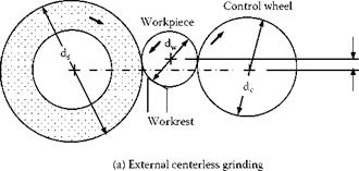
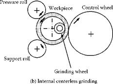
FIGURE 19.2 Basic centerless grinding processes.
where ds = grinding wheel diameter, dc = control wheel diameter, and dw = workpiece diameter.
It should be emphasized that Equation 19.1 is only an approximate guide. Detailed guidance on set-up values is given in sections below.