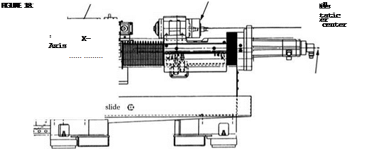
The selection of the appropriate load/unload mechanism is a major source of cycle time savings. Options include:
• Through-the-work-spindle loading. Small parts are fed through the workhead into a chuck. Each new part ejects the preceding part that falls or is held by a receiving arm. Grinding resumes as soon as the ground part and receiving arm are clear.
• Linear arm and two-arm loaders. Combination swing and linear motion for front loading. Single-arm version loads only the part being ejected into an unloading chute. Two-arm loader: latest designs use a combination of swing and linear motion with high-speed two-axis ac servo control.
• Flow systems to two-roll and shoe centerless support arrangements. A shoe centerless work support arrangement grinds the ID concentric to the outer diameter (OD). The latest flow or gravity-fed load devices can load/unload in 0.5 s [Toyo 2000, Toyo n. d.]. A gravity-fed loader is used with a simple ejector arm to kick finished parts off the shoes.
A variation on this is a two-roller and one-shoe arrangement.
18.5.7 Coolant
Coolant is more likely to be water-based than oil in the United States although the reverse is true in Europe. The difference in performance can be as great as the difference between fixed infeed and adaptive power grinding. For plain bores, coolant is supplied from both the front and back. For blind end applications through-the-spindle coolant is typical.
18.5.8 Gauging
Gauging is standard either as in-process as discussed above or more commonly postprocess using air gauges to measure size, taper, even profile. Typical systems will plot a running performance
 |
statistical process control (SPC) graph and make automatic adjustments on size and sometimes even taper. The systems average out the values of a given number of preceding parts (usually three).
