
A fixed infeed system has major limitations from the inability to adapt to changes in incoming stock or wheel conditions. Much research has been carried out to develop systems to control the system based on force either directly using normal force or indirectly by monitoring power (tangential force).
One of the earliest versions was the Heald controlled force system (CF) pioneered by Dr. Hahn and the Heald Corporation in the 1960s. This applied a controlled normal force from the wheel to the part via a hydraulic ram. By today’s standards, the system was relatively crude but highly effective for the appropriate application. Hundreds of these machines are still in production for plain bore applications.
Their use can be problematic when internal plunge profile grinding unless the incoming part preform is well controlled. In bearing manufacture, the race is previously turned in the soft state and then heat treated during which the bearing profile may often distort slightly. To compensate for this, the bearing race is turned to a smaller radius to ensure cleanup after grind. Unfortunately, this leaves excess stock at the two tangent points to the outer diameter. A CF-type process sees only the average force over the whole bearing surface to be ground and will plunge in a rapid approach rate through the excess stock leaving wear steps in the wheel.
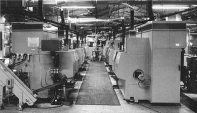
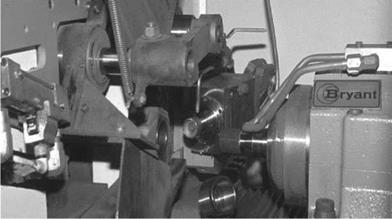
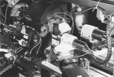
In the 1980s, with advances in closed loop ac servo drives, it became possible to closely monitor power. Initially, this was used to detect part contact during rapid approach and to control spark-out times based on decay time constants. The efforts culminated in the 1990s with controlled power grinders such as the Bryant UL2 (Figure 18.11 and Figure 18.12).
In this type of grinder, all the feed points are still fixed but all the infeed rate parameters are now at a fixed power level controlled by a fast-response power monitoring system. The control inputs include a stock load sensor for first contact, rough grind, a rough grind power trip differential for alox wheels (power must drop below a given level at a fixed feed point inner diamater (ID) to allow sufficient relaxation to safely retract the wheel when dressing midcycle), finish grind, and a spark-out power differential (power decays below a given power level). The grinder also takes into account the initial problems of break in for a new CBN wheel. After the initial wheel dress, the first parts are fed at a set percent of full feed power setting and then ramped up at a given percent
|
|
|
FIGURE 18.12 Universal-joint cup grinding arrangement. (Courtesy of GE Superabrasives. With permission.) |
increment every given number of parts. This prevents loading of the wheel when dull and allows a wheel several grades harder to be used increasing wheel life by up to a factor 5.
As the wheel wears through its life, its diameter can reduce by 20% and significantly affect the grinding conditions in a number of ways. First, the physical amount of CBN becomes less increasing wear and reducing parts/dress. Second, de, and, hence, contact length, is reduced allowing a faster infeed rate for a given adaptive power setting. Fast feedrates will further accelerate the rate of wheel wear. The Bryant UL2 has an equivalent wheel skip decay function option that allows the end user to input a parts/dress algorithm as a function of wheel diameter. This is nonlinear and can vary from, for example, 200 parts/dress for a new wheel diameter to as little as 10 parts/dress at minimum wheel size. In addition, to prevent the wheel getting too sharp and breaking down exponentially, there is CBN adaptive dress trip rate that is set to a given maximum allowed infeed rate. If this value is exceeded, the wheel is automatically dressed.
This system has allowed enormous improvements in CBN wheel life. Adaptive power grinding systems are now available from several machine tool builders either as software integrated into custom controls similar to that described above or as separate control systems that can be added to an existing grinder. In addition, some of the latest CNC controls have options available to control feed to a given power. Its use, though, is limited to a range of wheel sizes from about 6 mm diameter up to 30 mm. Below about 6 mm, the power signal-to-noise ratio is too low to get a clean signal while at diameters greater than about 30 mm the power detection and reaction times are not yet fast enough to prevent loading with harder CBN wheel grades. Linear motor technology is expected to improve on this.
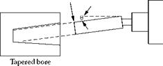
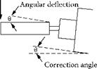
Systems based on normal force offer the ultimate in control as a direct measurement of system deflection. Hahn again pioneered work in the 1990s on direct measurement of normal forces and compensation for quill deflection. In a series of articles, Hahn analyzed the taper deflection problem and proposed a method based on detection of normal force, calculation of quill deflection, and microswivelling of the wheelhead to compensate [Hahn and Labby 1995a, b, Hahn 1997, 2000].
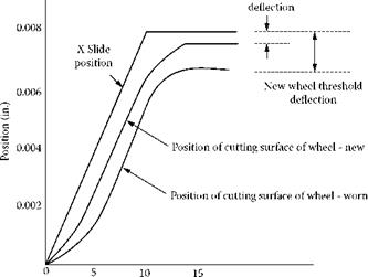
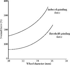
The system deals with the biggest factor that cannot be influenced by adaptive power control, namely, threshold normal force. Figure 18.13 plots a typical slide feed cycle for a simple rough grind and spark-out operation together with the actual position of the wheel for a new and used condition. As shown in Figure 18.14, the threshold forces at the end of cycle can be less than half for a worn wheel than a new one. This will result in a significant change in part size and taper over the life of the wheel regardless of spark-out time or roughing infeed rate.
Hahn developed a microangle/force sensing subplate to both measure the force and make the compensation for deflection (Figure 18.15). The system can also measure Work Removal Parameter A(=Q’/Fn), which is a key quantitative measure of wheel sharpness. Although Л cannot be measured
|
|
|
|
|
|
|
|

![]()
|
|
|
|
|
|
|
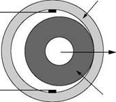
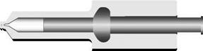
FIGURE 18.16 In-process diameter gauging.
directly using power only, it is a key parameter in determining maximum feedrates in weak systems limited by burn. Л is especially pertinent to alox wheels that become dull with time after dress and may cause burn if threshold forces are too high.
Having taper compensation based on normal forces also allows faster overall cycle times for weak systems susceptible to chatter. New wheels with relatively large de values can sustain relatively high feedrates without the onset of regenerative chatter. As de is reduced, contact length and regenerative chatter can occur faster. Normally the feedrates and wheelhead position are set to those that are stable for the smallest diameter. With taper compensation, faster feedrates may be used for larger wheels and algorithms applied to gradually reduce rates to those of the fixed infeed grinder as the wheel gets smaller.
Alternate systems based on measuring the physical deflection of a quill using opposed air gauges have reportedly been used in the bearing industry for some years. A system was recently presented by UVA [n. d.] called GPC-PSH, which provides the combination of a sensor in the spindle to measure deflection and a compensating method for swiveling the head. The method is claimed to improve straightness and cylindricity by up to 40% when grinding small fuel-injection components.
 |
|
 |
 |
Interest in force-controlled grinding is probably much greater than current original equipment manufacturer (OEM) publications and what literature would suggest. Competitive industries such as bearing manufacturers are very secretive with highly skilled research groups; several build their own grinders. The potential for CF grinding was presented in 1988-1990 by Heald in combination with The Torrington Company [Bell et al. 1988, Matson et al. 1990, Vaillette et al. 1991]. These papers focused on several of the aspects of controlled force grinding discussed above. Part of the
|
FIGURE 18.18 Twin wheelhead machine for seat and bore grinding of injectore. (From UVA n. d. With permission.) |
interest was in how to optimize the use of CBN that was then still quite new, and process optimization by, for example, gap elimination. Another area of research, however, was in the use of Л to help improve roundness. During rough grinding, once continuous contact has been made between the wheel and part, the level of eccentricity in the part is given by (Fmax — Fmin)/Ks where Fmax and Fmin are the maximum and minimum normal force, seen in the power consumption plot as a once-per-work revolution spike, and Ks is the system stiffness. The number of revolutions needed to round the workpiece up to an acceptable running truth is a function of system stiffness and Л. In the papers referenced, algorithms were used to automatically regulate the feedrates to ensure sufficient revolutions of the workpiece before reaching finished size.
In-process gauging is a common, if somewhat delicate, method of controlling size. Longanbach and Kurfess [1998] reported using in-process gauging for the real-time measurement of out-of — roundness, waviness, or chatter during grinding, which was incorporated into a production grinder.
AE-based sensors have also been applied to internal grinding. Inasaki [1991] reported on an AE sensor water-coupled to the wheel quill as part of an integrated system including power monitoring for developing unattended grinding. AE was used for gap elimination, dressing, and chatter detection. Several machine tool builders offer AE systems as an option for gap elimination and/or touch-dressing CBN wheels, although use of AE for dressing is still limited. Drake [2000] has incorporated the AE sensor in the wheelhead. Studer [2001] has incorporated a ring sensor into the work chuck flange for small wheel applications. EMAG/Reinecker [2001a, b], offer sensory analysis modules that include AE for gap elimination and dressing as well as power-controlled adaptive grinding. Similar options are offered by Toyo [2000] while Okuma [2000] offers AE for touch dressing CBN. Finally, the size of AE sensors has reduced to the point that they can now be fitted inside small dc servo electric dressers.