
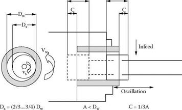
The selection of grain type has a significant impact on wheel length. Specifying of the length of an alox or ceramic wheel is based on the recognition that there is a significant level of wheel wear for each part that is ground. The length of the wheel is, therefore, kept short and the wheel oscillates a significant distance past the ends of the part to maintain straightness. The breakdown is sometimes so great that it is often dressed midcycle just prior to finish to re-establish size. Salmon [1984] makes the following general recommendations with reference to Figure 18.5 where the oscillation is a third of the wheel length past both ends of the part.
For CBN wheels, the wear is one hundredth the wear with alox and the goal is to maintain the straightness of the wheel face and avoid excessive edge breakdown. Consequently, the wheel is made about 1 to 2 mm longer than the length of the part and a much smaller oscillation stroke applied such that the wheel normally remains in contact with the full length of the part for all or most of the time. Small adjustments of the end points can be made to adjust for taper and shape in the part. For example, if the back of the part is small then the wheel oscillation end point is moved
|
TABLE 18.2 Recommendations for Alox Grit Sizes as Function of Part Size, Roughness, and Stock Removal Requirements
|
|
A A
FIGURE 18.5 Parameters for ID grinding with alox wheels. |
farther back past the end of the part such that the wheel contact length is now slightly less than the full length of the part. This gives more time for the wheel to remove metal where the part is small; in addition, the reduced contact length will reduce normal force and quill deflection further improving shape.
Using this method for taper compensation, any residual quill deflection, if it were constant from part to part, could be compensated for by adjustment to the wheelhead angle. Unfortunately, the normal forces change significantly both with wheel sharpness after dress and longer term with changing wheel diameter. The machine operator can attempt to adjust for these by either adjustment to the wheelhead alignment or the oscillation end points. This approach is often unacceptable both for the degree of operator intervention and the lack of process control.