
The roll grinding market covers an incredibly broad range of applications from rolls for business machines of just an inch or less in diameter to rolls for the steel industry that can weigh up to 50 tonnes. Workpiece materials include rubber, aluminum, steel, cast iron, ceramics, granite, and exotic metals and polymers. Often finish requirements must be held in a tight band of values, and surface integrity and cosmetic appearance, the elimination of feed lines, are paramount.
The largest areas of use, certainly in abrasive consumption, are the steel and paper industries. Rolls for the steel industry are made of either forged steel (48 to 52 HrC) or chilled cast iron. Finish specifications and tolerances are driven by whether the rolls are used in hot strip mills or cold strip mills, with the demands for cold strip mills being considerably tighter as they impart the final finish on the rolled steel:
Hot strip: 0.002" shape deviation, 0.0020" roundness, <40 p" Ra finish
Cold strip: 0.0005" shape deviation, 0.0002" roundness, <10 p" Ra finish
A typical wheel for a steel roll hot strip application would be 900 mm x 75 mm and would last about 100 hr grinding 100 to 150 rolls. Typical roll size (50 ton): 750 mm diameter x 1,800 mm long with 0.25 mm stock on diameter. Most wheels are either conventional resin or occasionally vitrified bonded.
Grinding wheel selection for cold strip rolls is governed by the need to eliminate regenerative chatter. Consequently, very compliant bonds are used such as shellac, resin, epoxy, and even cork abrasive.
Rolls for the paper industry are made from cast iron or chrome steel for general smoothing and calendaring while for some specialty applications, especially for fine paper production, granite and polymer granite are used. Rolls can be up to 1 m in diameter and 12 m long. The shear weight of these in operation creates a sag or bow in the center of the roll that can be a significant proportion of the paper thickness to be smoothed. Consequently, an inverse profile to compensate must be ground in the roll. Surface finish requirements are <0.4 Ra after roughing and <0.1 Ra after finishing.
Most modern machine tools can maintain 1.25 pm taper, flatness, and profile on rolls up to 300 tons. Leading OEMs include Waldrich Seigen, Herkules, Pomini, Toshiba, Capco, and Schaudt. Other machines common in the industry include Voith, Farrel, Churchill, Craven, Naxos Union, MSO, and INNSE. Small machines maintain the standard moving carriage design of a typical general-purpose cylindrical grinder, but the large machines for the steel and paper industries have a moving wheel head where the operator moves with the wheel while controlling the process.
A roll grinder consists of up to three independent slides on a massive casting. The whole machine is mounted on a massive isolation pad as in the example in Figure 17.40 of a Pomini machine.
The machine requires an extensive laser alignment upon installation or repositioning to the required accuracy while great care is taken in the design to minimize the effects of thermal movements. Residual repeatable slide errors can be compensated for in modern CNC controls.
The rear axis carries the wheelhead and its primary axes of motion X and Z. All slides are hydrostatic as, in general, is the wheel spindle. Grinders are also equipped with Y and U tilt axes
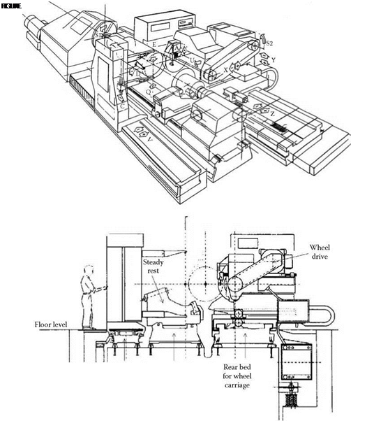
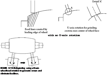
for microswiveling the wheel head. These are required to maintain a normal position against the part when grinding crown profiles in order to minimize feed lines.
All machines are equipped with at least a load monitor for the wheel spindle. On older machines, the operator will constantly infeed the wheel to keep the load constant. On modern CNC machines, the control will either infeed after every stroke or, more typically, at a continuous preset rate during the grind, or adaptively under constant load. This is to compensate for the very significant breakdown of the wheel.
 |
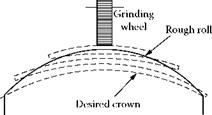
The control will also carry out short stroke grinds at certain positions in order to remove excess stock on a new roll or when changing crown (Figure 17.42). All the while the CNC is able to generate a taper, crown, or compound curve shape while compensating for bed error (Waldrich Siegen 1996).
The front or center bed carries the work head drive and tail stock. Being separate and rigid, it allows the isolation of any effect of loading a heavy workpiece. Usually at least one axis of adjustment is available for initial roll alignment and taper correction.
The third carriage carries the gauging equipment—a two-point dimensional measuring caliper with optional Rollscan, eddy current, and finish measuring attachments. A longitudinal V-axis moves the caliper independently of the wheel slide. If a separate carriage is not present, the gauging system rides on the rear carriage with the wheel head.
Older grinders without automatic gauging relied on the operator stopping the grind operation to measure the roll using manual calipers, and then feeding with higher load in those areas with higher stock—a process based on art and experience. Automatic gauging with roundness and shape fed directly into the CNC can now continuously measure and compensate.
 |
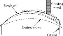 |
Short stroke TaPered ro11