
Whereas camshaft lobe grinding faces difficulties associated with cylindrical grinding, a nonround part at least, all lobes of the component are configured on a common centerline. Finish grinding of crankshaft pins may appear to be a simpler round grind operation but each pin is on a different centerline governed by the “throw” of the crank.
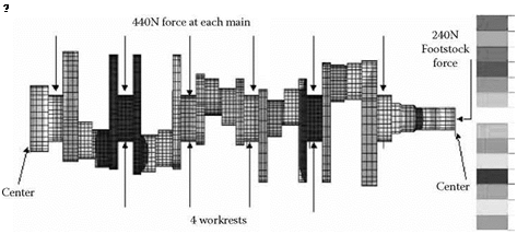
Additionally, the crankshaft is very weak and, hence, easily distorted if overclamped, is unbalanced at grind, and prone to “unwind” if the heat-treat is not carefully controlled. Consequently the first step in designing a grind process for a crankshaft is an FEA analysis of the clamping forces and foot-stock clamping pressures and a subsequent determination of steady or workrest requirements (Figure 17.38) [Pflager 2002].
|
|
|
|
|
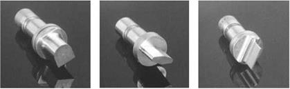
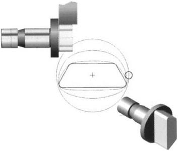
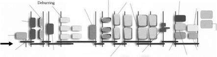
FIGURE 17.34 Punch profiles. (From Studer 2001. With permission.) |
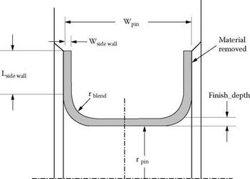
Cranks are made of either nodular iron in the 150 to 250 BHN range for automotive engines or steel surfaces heat treated in the 25 to 40 HrC range for higher power and diesel applications. Most automotive crank pins are first turn-broached to relieve the sidewalls and leave an undercut at each edge. This undercut is then fillet-rolled, resulting in a finish flat grind with about 1-mm stock performed using vitrified CBN abrasive. For diesel cranks, there is no undercut for fear of generating stress risers and the pin, edge radii, and side walls are all ground. Wheels must be dressed to the exact width and profile. Most of the stock now occurs on plunging the depth of the sidewalls and can be up to 15 mm (Figure 17.39). Special sandwich wheels with split grades are used primarily
|
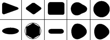
FIGURE 17.35 Punch grinding strategy. (From Studer 2001. With permission.) |


Wheel, gear Standard O. D. turning CNC lathe
Machine for tempering
Journal grinding CBN/CNC super high-speed cylindrical grinding machine
First balance machining Balancing machine

 |
 |
 |
Carry out final product Device to carry out Palletizing
FIGURE 17.36 Flow chart for a modern automotive crankshaft manufacturing line. (From UMS 2002. With permission.) with alox/seeded gel combinations although some vitrified CBN applications have been developed recently.
There are several machine design strategies for approaching the issue of grinding each individual pin on its centerline. The traditional method is to use a mechanical chuck to index each pin in turn onto its axis of rotation, and use automatic throw changers to compensate from one crank type to another. The chucks and indexing fixtures are complex, product-specific, and, being mechanical, potentially unreliable. The method loses a significant amount of cycle time for each indexing movement. An alternative approach developed in the early 1990s by Landis for high production, >200,000 cranks/annum, was to use simplified chucking on grinders dedicated to one specific pin [Anon. 1994]. The grinders were set up similar to a transfer line with a load/unload system that moved the crank from one single-pin grinder to the next until all the pins were ground. This reduced cycle time but at the risk that if a grinder had operational problems or required a wheel change then production was lost from all the grinders in the line. Fortunately, the reliability of modern grinder is such that, with proper preventative maintenance, down time from mechanical problems is minimal while CBN technology has pushed wheel life to as great as 3 years.
The introduction of vitrified CBN to crankpin grinding in the late 1980s allowed machine tool builders to completely rethink how crankpins should be ground. The ideal way to grind the crankpins would be with the crankshaft being rotated on the same axis as seen by the engine. This requires the wheel to be moved by the throw amount using a CNC control akin to a camlobe grinder. Such a concept was impossible trying to hold micron-size tolerances over throw lengths of the order of 100 mm with conventional wheels that varied in diameter during their life by 25% and wore microns/pin. However, it became practical with CBN wheels that varied in diameter by only 1% and wore nm/pin.
The process has been termed “CNC contour grinding” [Toenshoff and Falkenberg 1996], “pin chasing” by Naxos Union Emag (2002), or “CNC orbital pin grinding” [Anon. 1998a].
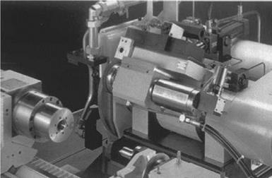
CNC contour grinding offers significant benefits in terms of flexibility, reduced tooling costs; for example, steady rest needs, elimination of complex work chucks, and a smaller machine footprint. Its greatest benefit, however, may be increased quality especially with regards to pin roundness. The standard automotive crankpin tolerance on roundness has historically been 5 pm, but with more stringent 2CpK capability requirements this has now reduced to 2.5 pm. The major source of out-of-roundness in most crankpin grinding operations is created by the presence of oil lubrication holes drilled into surface of the pins. These can be clearly seen in Figure 17.37. These
![]()
|
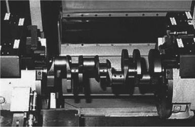
holes reduce the wheel/workpiece pressure not only by physically reducing the contact length, but, more importantly, by reducing the hydrodynamic coolant pressure. Depending on the stiffness of the crank, wheel speeds are typically limited to <80 m/s and finish grinding is carried out in “trickle” grind mode to reduce the out-of-roundness down to the order of 2 pm. With traditional grinding methods, this still consumes almost the entire available part tolerance and creates a very discrete and obvious dip in the roundness profile. CNC contour grinding with programmable crankpin angular position capability allows this 2 pm to be compensated for thereby improving overall roundness by 50%.
The drive for increased quality in crankpin grinding has, therefore, led to commonality in machine tool design with camlobe grinding to the point that machine tool builders are now offering a common machine for both applications and with the flexibility to grind mains, too. For example,
 0.0
0.0
-.7514
-1.503
-2.254
-3.006
-3.757
-4.508
-5.260
-6.011
-6.762
-7.514
-8.265
-9.017
-9.768
-10.52
|
FIGURE 17.39 Stock removal in diesel crankpin grinding. (From Corallo, Gridley, and Medici 1993. With permission.) |
the Landis 3L twin wheelhead nonindexing grinder illustrated in Figure 17.30 can be configured to grind camlobes and/or mains or crankpins and/or mains.
Interestingly, the grind process for a dual wheel pin grinder is much more complicated. For a constant workspeed, the instantaneous stock removal rate will vary from a maximum given by (rpm/60) • (stroke + pin radius) • infeed/rev to a minimum given by (rpm/60) • n — (stroke — pin radius)- infeed/rev. For a single wheel orbital pin grinder, it is possible to vary the instantaneous workspeed just like in camlobe grinding to even out the removal rate. When dual wheel pin grinding the problem is all the pins are out of phase with each other. This makes optimization of the workspeed more complicated. For a dual wheel arrangement it is also necessary to ensure the two wheel speeds are shifted by 1 to 2% to avoid regenerative chatter.
The most recent developments in crankpin grinding has been to marry together the CNC contour technology with modern plated CBN technology by increasing spindle motor power up to 80 kW and wheel speed up to 160 m/s. In conjunction with increased acceptance of oil coolant from improvements in its handling and containment, rough or “green” grinding has been gaining acceptance as a replacement to turn broaching. Laycock [1996] reported the following maximum stock removal rates for plated CBN wheels rough grinding cam and crank materials in oil:
Soft cast iron 360 mm3/mm/s
Soft steel 250 mm3/mm/s
Hard steel 200 mm3/mm/s
Pflager [2000] confirmed a more general value of >150 mm3/mm/s that is over 300% greater than hard turning and 50% greater than soft milling. Giese [1999] reported a plated CBN wheel life grinding pins including the undercuts of 40,000 to 60,000 crankshafts at comparable cycle times to turn broaching. Green grinding eliminated the need for the frequent replacement of carbide cutting tool inserts. Plated CBN has actually proved cost-effective grinding at half the cycle time of turn broaching. Since the machine tool’s cost for a high-speed grinder is comparable or less than the cost of a turn broach [Anon. 2000], green grinding offers significant capital equipment cost savings.
As speed and stock removal rates increase, limitations occur in the maximum power available for grinding. As discussed above, a narrow wheel reduces coolant drag losses making more power available to grind at higher Q values and, hence, additional removal rate capability as a result of the lower ec values associated with this. Several researchers and OEMs [TMW 1998, Toenshoff et al. 2002] have, therefore, proposed grinding pins and mains in multiple plunges to increase overall stock removal rates and increase flexibility to grind mains and pins of different widths.