A related, but somewhat simpler, process to camshaft grinding is the grinding of punches for the die and pharmaceutical industries. Profiles for punches are simple radii and straight faces and machine controls are set up with canned programs to generate a given shape with the operator entering a few basic dimensions. Batch sizes are relatively small so flexibility and rapid change over times are critical. Parts are held by the shank in a simple 3- or 4-jaw chuck. Computational
|
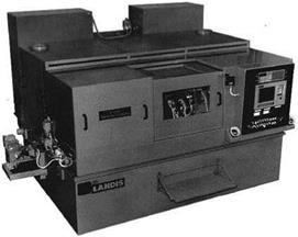
FIGURE 17.29 Landis 3L CNC single-wheel CBN camlobe grinder. |
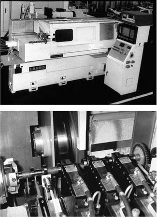
demands and workspeeds, while still demanding, are lower than in camlobe grinders as is the cost of the machine. OEMs include ANCA, Studer, and Weldon.
Most punches are made of tool steel making CBN particularly attractive where punch designs allow a constant wheel corner radius for the blend at the holder end. Cycle times are reduced by 30% [Kampf 2000] or greater over conventional abrasives using wheel speeds of 60 to 80 m/s in water-based coolant.
The problem areas for punch grinding are in holding sharp corners on square punches and holding taper values of 1 to 2 pm parallel and orthogonal to the punch axis as the result of wheel and coolant hydrodynamic pressure. Some errors in profile can be programmed out if they are consistent; others may require prolonged spark-out times if using alox wheels. For CBN wheels, however, the coolant can be switched off almost entirely during spark-out to relieve hydrodynamic effects. The technique is call “trickle” or “dribble” grinding and is even more pertinent to crank pin grinding.
There is also a different strategy required for how stock is removed compared to camlobe grinding. Punches are ordered in very small batches with a requirement to ship within 24 hr. Consequently, the rough stock coming to the grinder usually consists of a basic round, through — hardened billet to limit inventory and maximize flexibility. This can result in up to 30 mm of stock removal on larger parts. An optimized spiral wheel path to the final size is, therefore, key to cycle time reduction (Figure 17.34).
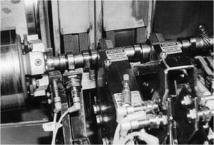
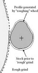
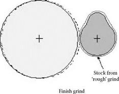
Rough/finish grinding of re-entrant camlobes with large roughing & small finishing wheels
|
|
FIGURE 17.32 Landis twin wheel camlobe grinder for roughing and finishing re-entry cam profiles. (From Pflager 2002. With permission.) |