
Camlobe grinding has been the leading driver of high-speed grinding over the last 25 years. It is a high-cost process, making up more than 40% of total camshaft manufacturing costs [Wedeniwski 1989]. The operation is very capital-equipment intensive resulting in pressures from end users to reduce cycle times while offering machine tool builders sufficient end sales volume to justify research into innovative processing methods. A flow chart for a modern automotive camshaft manufacturing line is given Figure 17.17.
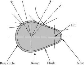
The finish grinding of the camlobe is one of the most difficult operations in the manufacture of an automotive camshaft. Profiles must be held at micron levels with equally tight timing angles, straightness, and finish requirements. The profiles are defined per degree of part rotation and
supplied as a lift table with either a series of length dimensions from the center point or as a deviation from the base circle diameter value. Figure 17.18 provides the terminology for the various features of the camlobe.
There are huge changes in equivalent wheel diameters going from the base circle through the ramp into the flank. On occasion, the flank may even have a “re-entry” or negative radius leading to near total conformance with the wheel, de ^^. Heat generation and burn are constant concerns at points along the flanks where conformance is greatest and/or the coolant is most masked from the grind zone. Thermal modeling of the process presented by Pflager [2002] illustrates the effect (Figure 17.19).
 |
Camlobe grinding has been transformed in the last 25 years. Prior to 1980, all cams were ground on master-cam grinders where the wheel slide movement was controlled by following a rotating template or master-cam. In the late 1970s, ac servo closed-loop systems with CNC controls to the work head were able to control the rotation while maintaining orientation of the camlobe in synchronization with movement of the wheelhead to CNC generate the profile. It was not long after this that machine tool builders realized that the accuracy required for generating cam profiles were the same as those required to implement CBN wheels. The first camlobe grinder reported in the literature designed specifically for CBN was manufactured by Toyoda Machine Works (TMW) and used resin-bonded CBN wheels. One such machine, a TMW GCB7-63, was supplied to Caterpillar about1980 to grind hardened-steel diesel camshafts [Hanard 1985]. The GCB7 had hydrostatic ways and wheel spindle, CNC profile generation, variable workspeed drive to control stock removal
|
100 200 300 400 500 600 700 800 900 1000 |
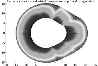
FIGURE 17.19 Temperature distribution with varying contact conformity (depth greatly exaggerated). (From Pflager 2000. With permission.)
around the camlobe, and an acoustic touch sensor to determine the relative position of the wheel and diamond truer. The wheels were 600 mm in diameter and, being resin-bonded, required a posttrue conditioning process using a dressing roll and free abrasive grains. This conditioning process was difficult to control and proved, together with the low resilience of the resin bond, to be the process-limiting factor. The wheel speed was only 50 m/s.
Following the fuel crisis of the 1970s, U. S. automotive manufacturers strived to improve gas mileage by improvements in engine efficiency. One area that was targeted was reduction in engine friction by using a roller rather than a flat tappet to transfer the lift from the camlobe to the valves. Rollers reduced friction but generated higher normal forces that were found to exceed the strength of the cast iron materials in use at the time for camshaft fabrication. This, in turn, forced engine manufacturers to switch to hardened forged steels.
Hardened steel proved to be considerably more difficult to grind than cast iron because it was sensitive to grinding burn due to the formation of untempered martensite, a brittle layer causing spalling and premature cam failure. Steel forgings or assembled cams, despite having only a third the stock of cast iron casting, proved impossible to grind in the hardened state in comparable cycle times to cast iron camshafts.
Two different manufacturing strategies were, therefore, pursued by different engine manufacturers to overcome this problem. Some elected to grind the steel in the soft state, where burn was not an issue, then to heat-treat. This route led to diminished dimensional accuracy due to thermal distortion in the heat treatment. By contrast, Ford Motor Co., for example, demanded grinding in the hardened state and proceeded to develop the technology first by assessing continuous dressing and then by adopting plastic-bonded conventional abrasive wheels. By the mid-1980s, this had become the standard processing route for much of the industry.
In the 1980s, increasing the Environmental Protection Agency’s demands for fuel economy, combined with improved emissions, led engine designers to make radical changes to the camlobe. “Re-entry” profiles were designed with concave radii of less than 350 mm in the ramp areas to speed up the rate at which engine valves open and closed. This further increased the risk of thermal damage during grinding because of the increased contact length. It also created a far more fundamental problem: production grinders of the time all used conventional wheels with a usable diameter
range of either 750 to 600 mm or 600 to 450 mm. This was totally impractical to meet production for the new camlobe designs.
In 1984, Suzuki described the first results from a CBN camlobe grinder dedicated to grinding with vitrified CBN wheels. In line with camshafts still made in Japan, the data reported was grinding cast iron. The grinder, a TMW GCH 32, is described in detail by Tsujichi (1988). It had a fixed wheel speed of 80 m/s, this being considered the “state of the art” in high speed at that time. Wheels for this machine had been developed by TVMK, a joint venture between TMW and Unicorn Industries [Hitchiner 1991], and were only 350 mm in diameter to allow the machine to be designed with a small footprint.
In 1985, Ford completed the design for its 3.8 L V6 engine with incorporation of a steel camshaft with the first re-entry (concave) ramp profile. Ford Manufacturing, faced with the capacity issue of a production line making 750,000 cams/year, elected to purchase 16 of the GCH 32 machines and committed themselves to “making them work.” This line was the first major installation of its kind in the world and represented the seminal technological and engineering R&D experiment to determine the viability of CBN for cylindrical grinding [Renaud and Hitchiner 1991].
There was no doubt as to the improvement in quality or ability to make capacity. The main problem was striking a balance between wheel cost/part by using hard grades and eliminating burn by going softer. This was a foretaste of the question of the optimum wheel speed for a given abrasive and application. The solution was to lower the wheel speed from 80 m/s to 60 m/s, which tripled wheel life.
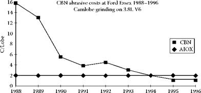
Figure 17.20 gives the abrasive cost/part for the first 9 years of the machine’s installation. After process optimization, the abrasive costs were well below those of conventional wheels grinding a non-re-entry profile cam. The biggest improvements though were in quality.
Some of the achievements listed include:
• 1992 Zero defect award for zero defects reaching assembly lines
• Several Perfect Performance Audits
• Machine uptime of greater than 95%
• Only one camshaft in over 4 million returned from an engine in the field. This was traced to loss of grinder machine power due to lightening and was subsequently eliminated as a potential process problem.
• One operator for 18 machines (two additional grinders installed in 1992)
• One wheelwright for all wheel changes on a two-shift basis; changes scheduled several days in advance (average one wheel/week for the complete line)
|
|
|
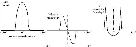
Lift Velocity Acceleration FIGURE 17.21 Lift, velocity, and acceleration profiles for 1 rotation of the camlobe. (From Landis 1996. With permission.) |
Ten years after 60 m/s was established as the optimum speed for grinding hardened steel with vitrified CBN in water-based coolant, machine tool and wheel technology have improved this to about 90 m/s. They have also tripled stock removal rates from Q = 10 to >30 mm3/mm/s.
In the rest of the world, with the exception of diesel truck engines, most of the camshafts have remained cast iron-based. Consequently they saw far fewer problems using CBN. Also Europe used oil coolant far more frequently. Wheel speeds of 80 m/s to 100 m/s worked well at Q values of >50 mm3/mm/s. In recent years, with machine tool improvements, these values have now reached as high as Q >180 mm3/mm/s at 160 m/s.
Today there are probably far more grinders in Asia running at 160 m/s grinding scooter, motor cycle, and small car cams than there are in the United States at this speed for all grinding; such is the importance of selecting the right application and material type for high speed grinding.
Grinding camshafts is in large part a geometry problem, or to quote Pflager [2000], “The problem with cams is that they are not round.” High-speed grinding with high removal rates requires high workspeeds. The challenge of the machine tool builder is to generate slide movements that can produce these accurately at the required speed.
Machine movements are limited by the dynamics of the machine; namely, its velocity, acceleration, and jerk (rate of change of acceleration) limits, which must be calculated at all points around the lobe. This must be combined with the lift data at each degree and produce a smooth transition-free surface. The angular resolution has, therefore, to be much finer with positional resolution calculated to as many as 10 significant figures. Rotational speeds in older machines were usually limited as much by control computational speeds as machine dynamics.
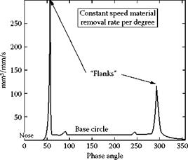
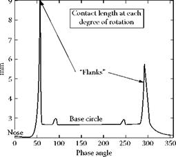
The workspeed rpm on the base circle is constant and defines the stock removal rate for general definition of process capability. As the wheel moves from the base circle through the ramp to the flank area, the workspeed must reduce rapidly. Since this time is finite due to the inertia of the system, there is a brief period where the contact length and stock removal rate both jump dramatically leading to a significantly higher Q value. Although near instantaneous, this can be the life or cycle time-limiting factor for the wheel (Figure 17.22 and 17.23).
The earliest machines were limited to about 100 rpm for workspeed based on computer speed. More recently, workspeeds have increased to over 300 rpm not only by control advances, but also by the use of linear motors to reduce the inertia of the wheel slide. This has allowed a reduction in peak Q values and thus pushed up base circle stock removal rate capability. Current Q values are typically 20 to 40 mm3/mm/s for hardened steel and 70 to 200 mm3/mm/s for cast iron.
During roughing the workspeeds are usually set at about 20% over the theoretical limit for maintaining the profile within tolerance. This is to maximize stock removal without thermal damage.
|
FIGURE 17.22 Q against phase angle around camlobe at constant work speed. |
Finish grind workspeeds are held at 20% below the limit for maintaining profile. The stock amount in finish should be greater than the depth at which thermal damage may have been generated during roughing and is typically 50 to 125 pm.
The sensitivity to burn of the grinding process for hardened steel cams in particular is such that nondestructive inspection methods based on Barkhausen noise have generally been adopted on many production lines [Fix, Tiitto, and Tiitto 1990]. Barkhausen noise is an inductive method that measures the noise generated by the abrupt movement of magnetic domain walls under the application of an alternating magnetic field. When a coil is placed near the sample, the change in magnetization created by the shift in the domain wall induces an electrical pulse. The sum of all pulses from all domain movements within the sample area provides the final signal or Barkhausen noise amplitude (BNA).
The BNA value is sensitive to several factors including the microstructure of the steel, hardness, and surface finish. However, for a given grade of steel kept within the standard limits of the process,
|
|
the biggest factor affecting BNA is residual stress. In particular, the relaxation of compressive stress cause by retempering can be detected by an increase in BNA signal. This increase is directly correlated to the severity of the thermal damage so long as the transformation temperature is not exceeded. If the severity of the burn is such that untempered martensite is formed, then the signal actually drops; therefore, the method is primarily for ensuring a process stays in control at a level well below the point that significant softening of the steel occurs.
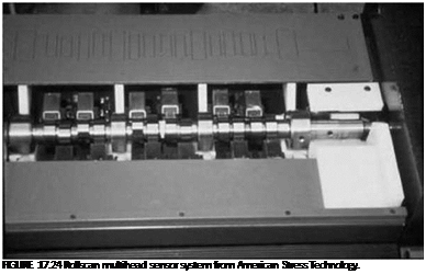
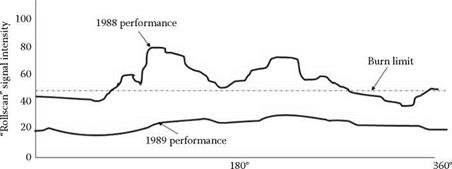
Figure 17.24 illustrates a Rollscan multihead sensor system from American Stress Technology. The system simultaneously measures all 12 ground lobes of an AISI 1050 steel camshaft. The system must be calibrated by using master cams checked for various levels of burn by Nital etching (Figure 17.25).
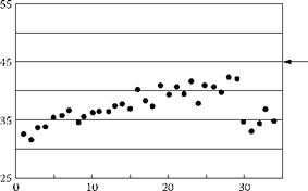
The value 50 is nominally set at burn, 45 is the upper process limit, while the process is under control for values less than 40. Figure 17.26 illustrates the change in BNA value on camshafts ground with a vitrified CBN wheel as a function of parts after dress.
In this case, at 80 m/s the chip load was too low and the wheel was glazing leading to increased grinding power. Thermal damage increased such that the wheel had to be dressed after just 30 parts. The signal could also be plotted as a function of angle around the lobe. Figure 17.27 plots the BNA values around a lobe during optimization studies. The initial cycle 1988 with high levels of
|
Number of pieces FIGURE 17.26 BNA variation with parts after dress (dress every 30 pieces). |
BNA shows peaks in the two ramps as predicted from the temperature analysis in Figure 17.19. This also correlated with Nital etch checks.
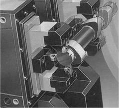
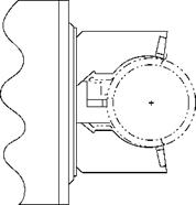
Camshafts are inherently weak. They have hollow centers for weight reduction that are preground on the journal surfaces prior to the lobe grind operation. During lobe grinding, the journals are supported by steady rests with flat polycrystalline wear shoes (Figure 17.28).
Any chatter that may have been generated grinding the journals will translate directly to the lobe grind. Furthermore, steady rests are relatively expensive and, therefore, limited to the minimum number to achieve acceptable part quality. Steady rests based on three-point contact may also cause buildup of chatter just as in centerless grinding if incorrectly adjusted. Too hard a wheel grade can readily cause chatter and profile errors from pushoff of the part. Tailstock pressure is applied hydraulically: too little pressure allows the part to bow due to the grinding force while too much will induce bow in the part and create taper. Similar taper problems can be created by incorrect setup of the steady rests. Identification of the root cause is usually achieved by evaluating the change in taper from one lobe to the next.
Camshafts can have up to 16 lobes or more with several in the same rotational phase. This offers the opportunity to grind two lobes at the same time. This concept has been taken further by building
|
Improvements to cam grinding process
Base Opening Nose Closing Base circle ramp ramp circle FIGURE 17.27 Rollscan multisensor system and readings. |
|
|
|
|
twin wheel head machines with two independently moving wheel slides. This allows two twin wheel sets with different spacings between the abrasive sections to be used for added flexibility. Up to four lobes with two different spacings can be ground simultaneously (Figure 17.30) [Landis 1996].
Re-entry profiles for most engines for the U. S. market can be ground using wheels of >300 mm. However, smaller engines, especially for the European market, use smaller cams with, therefore, smaller re-entry radii. These have necessitated wheels as small as 50 mm.
For this type of application, an alternative approach has been required: to rough the camlobe using a large plated CBN wheel and to finish and generate the re-entry profile using a small vitrified CBN wheel. The process is carried out in oil coolant to achieve the economics using plated CBN. The wheel speed for the vitrified wheel is limited due to size to <100 m/s. The smaller wheel spindle is on either a vertical slide [Pflager 2002] or a swing-down arm [Schaudt n. d.] to prevent interference with the larger wheel.
These machine configurations created two additional benefits. The first was that since the small wheel was finishing only, it could be specified to produce a lower surface finish than a wheel required to rough and to finish grind. In some circumstances, this allowed the elimination of polishing—a postgrind process using conventional abrasive film and as expensive in terms of consumables as the grinding process itself.
The second benefit related to grinding diesel camshafts. Gasoline camshafts have intake and exhaust lobes; a diesel camshaft has an additional injector lobe, which is typically a different width to the other two types. Diesel camlobes also have extremely stringent straightness specification of <1.25 pm, which is comparable to the break-in depth of a vitrified CBN wheel. When trying to grind all three lobes with one wheel, a step is rapidly formed and the process becomes uneconomic. However, a twin wheel machine with the small auxiliary spindle configured with two vitrified CBN wheels can contend with the different widths.