
Since the mid-1980s, the Institute for Machine Tools and Factory Management of the Technical University Berlin worked on an analytical description of the relative motions in cycloidal restricted guidance on lapping machines. A model was developed that calculates the profile wear of the lapping wheel as a function of the path curves of the workpieces on the wheels [Spur 1997, Simpfendorfer 1988, Uhlmann 1999].
For all machines with fixed external pin circle, selectable kinematic parameters are the rotational speeds of the lower grinding wheel щ, the upper grinding wheel nu, and the internal pin circle щ. Thus, a description of all path types and velocities related to the lower grinding wheel with the rotational speed ratio
![]()
![]()
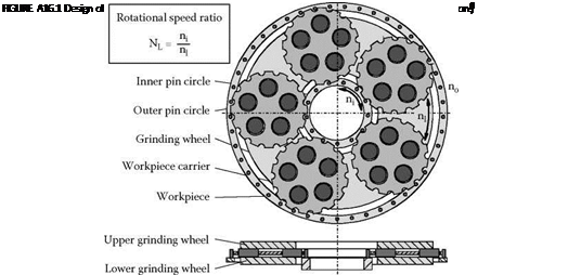 |
n
__ l_
n is possible. Nl describes unequivocally for a single machine the path type on which the workpieces move relative to the lower grinding wheel. All path types can be covered with different velocities within the scope of the possible rotational speeds of a machine [Ardelt 1999].
A16.1.3 Analysis of Path Types and Velocities
In the following, the connection between rotational speeds and emerging path curves is explained [Ardelt 2000]. This kinematic analysis depends on the diameters of the grinding machine design. In this example, it’s done for a machine type Duomat ZL 700 by Stahli Lapp-Technik GmbH, Germany. The outer pin circle of this machine is fixed, whereas the two grinding wheels and the inner pin circle can be driven individually.
Figure A16.2 shows the characteristic path types that a workpiece center point covers as a function of the rotational speed ratio, NL. The path types designated with letters are classes, which occur in certain ranges of NL. The curves marked with numbers are special cases that arise only at a definite ratio of the two rotational speeds.
|
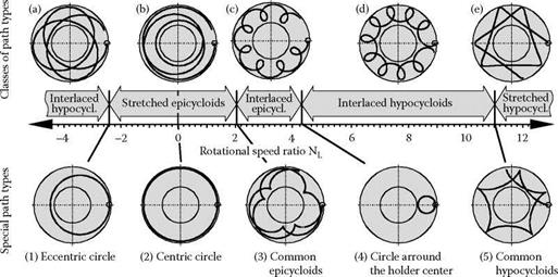
At high negative rotational speed ratios, all workpiece points cover stretched hypocycloids (a) on the grinding wheel. These path curves turn into stretched epicycloids (b) at -2.39. At the transition between these two path types, the parts move on eccentric circular paths around the grinding wheel center (1). Whereas the cyclically recurring shape elements of all path types with NL < 0 wind around the center of the grinding wheel, tight loops with strong bends emerge at NL > 0, repeating themselves on one half of the wheel coating. At a rotational speed ratio of 2.15 the stretched epicycloids become interlaced epicycloids (c). At the transition point common epicycloids emerge which show a reversing point in the form of a buckling (3). With increasing rotational speed, ratio circles around the holder center (4) occur which represent the transition point to interlaced hypocycloids (d). At NL = 11.09 common hypocycloids (5) emerge which turn into stretched hypocycloids (e).
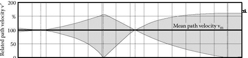 |
The occurring relative velocities are shown in Figure A16.3. The graph gives the mean path velocity by 100% and the occurring maxima and minima related to this mean value for every rotational speed ratio. The path velocities vary more or less strongly depending on the shape of the curves. The related path velocity V(t) given in the diagram is defined as the ratio of the path velocity v(t) to the
e
Stretched 1 hypocycl. (
І і і і і і і і і і і і і і і і і і і і і і і і і і і і і і і і і і і і і і і і і і і і і і і і і і і і і і і і і і і і і і і і і і і і і і і і і і і і і і і і і і і 11
-4 -2 0 2 4 6 8 10 12
Rotational speed ratio NL
mean path velocity vm. If the lines for minimum, mean, and maximum velocity intersect, the occurring path curves are covered with constant velocity. This effect occurs at NL = -2.39 and 4.35. As could be seen in the previous graph, circular path types emerge for these two rotational speed ratios. Covering common epi — and hypocycloids at NL = 2.15 and 11.09, the workpiece points minimum velocity is zero. On these path types, the workpieces are exposed to extreme differences in velocity, which alternately reach a momentary standstill and an acceleration to over 150% of the mean path velocity.
Figure A16.2 and Figure A16.3 demonstrate that the kinematic conditions at equal mean path velocity depend heavily on the rotational speed ratio and thus, on the shape of the path curve. To explain this effect, Figure A16.4 shows two different workpieces moving along a stretched epicycloid path. Along this path curve, the relative velocity increases from the inner to the outer grinding wheel diameter. In a certain grinding time interval Atc, workpiece A moves a longer track length than workpiece B does due to their different velocities.
The upper grinding wheel descends simultaneously on all the workpieces. Thus, the achieved workpiece height difference after Atc has to be the same for all workpieces. This means that for the mentioned example, in spite of the different relative track length, both workpieces A and B lose the same height. It follows that the angle of grinding grit engagement has to be different for both workpieces, as the velocity vectors in Figure A16.5 show. This effect strongly depends on the type of relative movement and on the distribution of relative velocities as a function of the lower grinding wheel radius.
Different angles of grit engagement may lead to different types of grit wear. It is possible to have one area of the grinding wheel surface working in the self-sharpening range, while another area shows grit flattening and loses its sharpness and grinding ability in short time. To set up stationary grinding processes, it is necessary to have equal microscopic wear conditions on the complete contact area, which can be achieved by analysis of the process kinematics.