
As discussed above, the problem with double-disc grinding is generating and maintaining flatness. This is either from the inherent limitation of trying to generate a flat surface while through-feeding into a wedge grind zone, or in the case of the slower infeed methods, maintaining a flat wheel with large differentials in surface footage from the outer to inner diameter.
Lapping kinematics using parallel plates is much better at maintaining wheel flatness and several lapping machine tool builders have taken this concept and made grinders using lapping kinematics together with superabrasive wheels. Although the removal rates are still much lower than a through — feed double-disc grinder, the grind is done in batches with coverage of up to 15 to 20% of the plate area, which can be 100 or more components. Consequently, cycle time/part becomes competitive with other grinding processes while grinding is done under controlled pressure and at low wheel speeds to minimize the risk of thermal damage or distortion.
The earliest efforts were initiated in the late 1970s by OEMs such as Hahn and Kolb using alumina and silicon carbide abrasive. The process was called “flat honing” [Stahli 1998] or “fine grinding” [Anon. 1996b]. This was able to demonstrate the viability of a fixed-abrasive process but wheel wear, and the associated dress time and operator intervention, was often a limiting factor. Although a number of these machines are running very successfully, grinding with superabrasive wheels was subsequently pioneered with European OEMs such as Wolters [2000, n. d.], Stahli [1998], Melchiorre [n. d.], and Modler [n. d.].
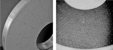
Wheel design for fine grinding can take several forms based either on a 100% covered, segmented face with coolant slots or holes, or as pellets (see Figure 16.73). Wheels requiring low coverages use round pellets, while hexagonal pellets are used for packing >90% or to keep gap distances low while grinding small parts. Pellets offer the potential to infinitely vary abrasive coverage across the face of the wheel in order to fine-tune wear. They also provide good coolant access and swarf clearance. However, they are still problematic for small parts and more expensive to fabricate than segmented wheels especially when a high coverage is required.
The wheels are bolted to flanges that have a sophisticated internal labyrinth of coolant channels to control temperature. The coolant itself is fed through holes in the upper wheel. Low-viscosity oil is the coolant of choice, especially in Europe, although some water-based oil has been tried in
|
|
|
|
|
Excessive wear on the bottom wheel with the top wheel conforming over time. Check carrier direction and speed. Actions (a) Decrease the velocity of the upper wheel.
(b) 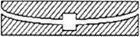
![]()
![]()
 Increase the velocity of the lower wheel.
(c) Increase the differential velocity of the carrier and the lower wheel near the wheel inner radius.
For the reverse wear condition reverse the recommendations.
Excessive wear in the ring circle of the carrier.
Also excessive wear on bottom wheel.
Actions (a) Reduce number of parts in the center of the carriers.
(b) Observe effect of (a) and if necessary then follow the recommendations given in 1/above depending on shape.
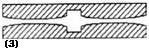
Both faces convex. Not enough parts in center of carrier or direction of carrier is being changed too often. If both faces are concave the reverse is true.
Action (a) Adjust part distribution in carriers accordingly.
FIGURE 16.76 Parameter adjustments for grinding wheel and ring carrier wear. (From Stahli n. d. With permission.)
the United States albeit with reduced wheel life. Wheel speeds prior to about 2000 were for the most part comparable to those used for lapping (1 to 3) m/s. This is, in part, historic but also, in part, to keep heat generation to a minimum with only limited coolant access. More recently, however, speeds have increased significantly with machine tool builders pushing the envelope up to 10 or 15 m/s. In doing so, coolant delivery and regulation have becomes much more critical as has spindle power, chiller systems, and stiffness.
Spindle horsepower is very dependent on table size and is typically double the power required for lapping because of the higher metal removal rates.
Wheel sizes are large with 700 to 1,000 mm being most common. With the additional power available for grinding, the machine and tooling must be more rigid and rugged to withstand the extra forces. Downfeed systems are predominantly pneumatically controlled [Lapmaster, Stahli,
|
TABLE 16.12 Wheel Spindle Power Requirements for Fine Grinding Machines OEM Data from 2000 and Earlier Wheel Diameter
[Wolters] |
|
TABLE 16.13 Maximum Grind Pressures against Wheel Diameter
Source: From OEM, data from 2000 and earlier. With permission. |
and Wolters], but hydraulic [Modler] and mechanical servofeed [Melchiorre] have also been used. The upper wheel head assembly is so heavy that the system is generally providing upward force to keep from allowing the full weight of the head to be applied to the grind. All grinding is carried out under controlled pressure. Pressures are expressed within the industry in “deca Newtons” or daN, where 1 daN = 10 N or 2.25 lb.
Taking the machine design values for pressures and wheel dimensions, together with the fact that the table has a 15 to 20% surface area coverage of components, maximum working pressures for grinding are in the range 7 to 21 N/cm2 or 10 to 30 lb/in.2, which is about double the pressures used for lapping.
Size is monitored in-process by a probe in the center of the spindle assembly and relies on the wheels wearing at submicron levels per load. The ability to monitor size is the limiting factor on cycle time as, in many cases, grinding removal rates can be up to 20 times faster than lapping. With the latest developments in bond technology and machine design, wear rates per load are often 0.2 pm or below.