
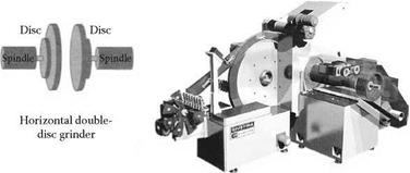
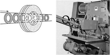
Double-disc grinding is a high-production, high-accuracy processing for parts with flat and parallel sides. Two opposed grinding wheel discs mounted on separate spindles simultaneously grind opposite and parallel faces on components fed between them by a variety of techniques. Doubledisc grinders can be configured in either a horizontal or vertical configuration referring to the axis of wheel rotation. Horizontal grinders are generally used for mid-range part sizes while vertical grinders are used for either very thin or very large parts.
The grinders require extremely high radial and axial stiffness. Most are either designed around a combination of large axial thrust, angular contact, and roller bearing combinations [Daisho n. d., Diskus 1996, Koyo n. d.], or full hydrostatic [Mattison 2 n. d., Kubsh 1998]. The motor drive is
Loading chute
![]() Loading and support shoe Superfinish
Loading and support shoe Superfinish
^ …………………………..
In-process gauge
Infeed drive
Rotating
backstop
Workpiece
Cup wheel
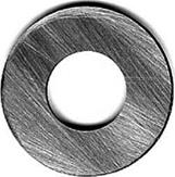
Convex-Concave adjustment
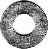
Cross-hatch adjustment
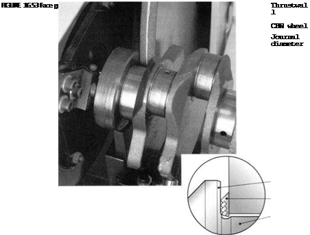 |
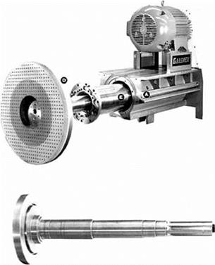
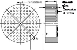
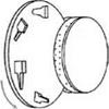
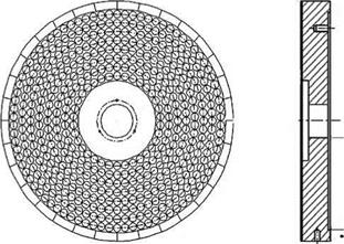
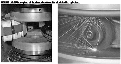
usually a synchronous or servo ac belt drive rather than a direct drive because of space limitation of the machine configuration. The spindle shaft and wheel-mounting surface are made from a one-piece steel construction with coolant passed through the center. The wheel is supplied either as an abrasive layer bonded to a steel back plate or as a layer with nuts inserted into the back face, which is in turn bolted to the spindle wheel mounting face. The components of double-disc spindle [Landis Gardner 1989] and wheels are shown in Figure 16.56 and Figure 16.57. Coolant, passed through the center hole, is disseminated over the surface of the wheel with slots while holes relieve the pressure and provide chip clearance and coolant access.
 |
Most wheels for double-disc grinding are resin — or plastic-bonded running at speeds of 35 m/s or less. Resin and plastic bonds can withstand more lateral strain and abuse than other more brittle bonds. Some oxy-chloride bonds are still used with conventional abrasives for the cutlery industry for dry grinding or where cool cutting is critical. Vitrified bond usage has been increasing especially
 ГГ! S tttft StfT" ttr; ;
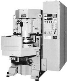
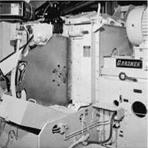
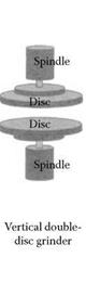 FIGURE 16.55 Vertical double-disc grinder. (Courtesy of Koyo Grinder. With permission.)
 |
with CBN for finish grinding on small machines specifically designed for using superabrasives. There has also been some interest in the spring grinding industry for electroplated CBN. Anker [1998] reported success in ends grinding of springs dry at 60 m/s on small purpose designed machines using coarse grit ABN 600, although resin-bonded CBN is more common, especially in Japan.
 |
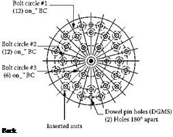 |
FIGURE 16.57 Components of a double-disc wheel.
Conventional abrasives still dominate virtually all general roughing processes and commercial — type finishing and semifinishing operations. 16#-36# grit is used for rough grinding, 36#-80# for commercial finishes and tolerances, and 60#-150# for fine finishes and tight tolerances. It is only in this latter category that CBN, in particular, has been competitive with grit sizes in the range of 100#-600#. Deming and Carius [1991], for example, reported good success grinding hydraulic pump vanes on retrofitted Besly double-disc grinders using 30 resin CBN wheels although they note on new dedicated machines the wheel size was reduced to 23.
 |
Since thickness and flatness control is critical, the grinder should be kept in a temperature — controlled room with the coolant chilled to ambient. Some manufacturers even keep workpieces in a coolant bath before grinding so as to stabilize the temperature. With coolant passing through the center of the spindle to remove heat, thermal growth can be held to a minimum. This is further aided by the machine configuration and spindle design inherent in double-disc grinding such that
|
FIGURE 16.59 Automated dressing cycle for double-disc grinding. (From Mattison 2 n. d. With permission.) |
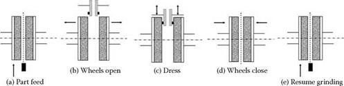
there is a tendency to compensate for thermal growth in the base with growth in the opposite direction for the spindle [Schlie and Rangarajan 1987]. Nevertheless, this is not perfect and compensation must still be added for wheel wear so postprocess gauging is common on precision operations. Timed compensation is more common for commercial tolerance work.
Conventional wheels are dressed using either stationary diamond or star cutter dressers mounted on a powered radial arm dresser that swings between the two wheels dressing both at the same time. The face of each wheel is dressed flat in relation to the spindle alignment regardless of the head setting. For resin and CBN, the radial arm has on occasion been retrofitted with a rotary dresser for truing in combination with either a grit blast-type conditioning process or stick dressing. Resin diamond wheels are almost exclusively dressed using dressing sticks.
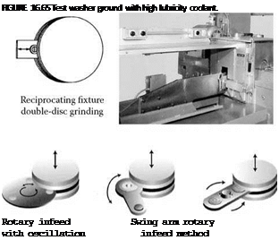
There are a variety of techniques for double-disc grinding depending on the stock removal and part tolerance requirements.
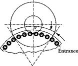
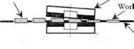
Rough grinding with the highest removal rates use through-feed grinding in a shear mode. Through-feed grinding involved feeding the parts supported by rails top and bottom through the center of the wheel. The parts are driven at the entrance of the wheels by belts in contact with the side of the part. Passage through the wheels is driven by contact with the part behind. The wheels are angled with a “head setting” such that the gap between them is narrowest at the entrance where 75% of the stock is removed. Often two or even three grades are used across the face of the wheel to allow for changes in surface footage and prevent burning in the center portion where only rubbing occurs. The wheel wears over time causing a step to move progressively over the wheel face and toward the center.
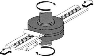
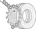
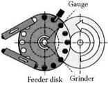
Higher precision is achieved by progressively grinding using a rotary feed or carousel method. In this case, the wheels are again angled but the maximum clearance is at the exit. The parts are fed in a rotary carrier with pockets that closely match the part shape. Small parts, especially those with a high aspect ratio, are sometimes rotary-fed by a geared-tooth inner ring surrounded by a smooth outer ring.
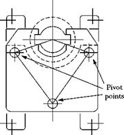
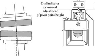
The calculations for the feed geometry and head settings are relatively straightforward. The carousel should pass over the wheel such that the centerline of the part cuts the inner diameter of the abrasive face. Wheels for rotary grind double disc have a large center hole in order for limited variation in surface footage across the face. Most spindle heads have three or four bolts at pivot points that can be raised up and down and monitored by a portable micrometer. The adjustment can be as simple as a single nut or a series of lockscrews and adjusting screws. There is some debate as to how the stock should be removed. For conventional wheels, the entrance gap should take 20 to 40% of the stock by shear grind with the remainder removed as it passes through the wheels [Doubman and Cox 1997]. For CBN, however, the cut should start about 20 mm into the wheel such that the outer surface of the wheel is kept wear free to just finish grind for flatness.
The wheel should initially be set at zero and then simple geometry allows a ready calculation for how much the entrance and rear pivot points need to be raised in order to equalize stock removal
|
|
|
FIGURE 16.60 Double-disc grinding arrangements. (From Landis Gardner 1989, Diskus 1996. With permission.) |
along the whole grind path. The entrance should then be double-checked for clearance with an unground part with the wheels stationary.
Again, two grade wheels are sometimes used. For example, one design by the author uses a combination of coarse grade CBN pellets for rough grinding (for reducing contact area) with a fine grit CBN continuous rim. This increased stock removal capability on one application by a factor 3.
On a vertical disc grinder, the bottom wheel should be set slightly higher than the exit plate. The parts should fit snugly in the carrier. Special attention should be paid in the case of round parts as flatness can be significantly improved if the part is allowed to spin in the holder. The spin is generated by the relative surface footage seen by one side of the part relative to the other. Obviously, the spin can be greatly enhanced by rotating the wheels in opposition but this creates too much wheel wear and can damage the carrier. The wheels are, therefore, rotated in tandem with a small difference in rpm between the two to vary the spin. Excessive spin will cause wear of the carriers that are often made of only mild steel or fiberglass. In some cases, carbide inserts are added to prolong life. The spin is such an issue that it can often be the primary factor governing the selection of coolant. Too high a lubricity can cause the part to lose traction and spin sporadically or even hydroplane. For this reason, double-disc grinding often uses synthetic coolant even with superabrasives.
|
|
|
|
FIGURE 16.63 Two-grade combination pellet and continuous rim superabrasive disc wheel. |
Coolant is delivered through the center of the spindle but must be dispersed by means of a baffle or other device to fling the coolant outward. This is made more difficult by the presence of the carrier. For thin parts, the carrier can warp and may well end up being ground on occasion leading to an increased risk of burning.
For the highest precision, through-feed grinders are typically small, compact, and use superabrasives. Examples include the Koyo models KVD 300 (305 mm wheels) and KVD 450 (455 mm wheels). Very few examples exist of larger wheels except for some older references to grinding pump vanes with 23 vitrified CBN [Navarre 1986, Landis Gardner 1989], and for finish grinding of piston rings with 600 mm resin CBN wheels taking 20 pm or less of stock [Buthe et al. 1996]. The problem relates to the difficulty in achieving sufficient stiffness, especially from the cantilever effect that comes into play with the larger diameter wheels as the part exits.
Through-feed grinding, in general, has problems achieving precision tolerances in a single pass with an acceptable cycle time when heavy stock removal is involved (>200 pm). The alternative is to infeed the wheel with their faces parallel. Several variations on this method exist. One method is to reciprocate or gun-feed a part between the wheels with linear oscillation. This is particularly effective for controlling wheel flatness when grinding large workpieces.
Alternatives include some form of rotary carrier or swing arm. The carrier may have its own drive mechanism to make the part spin to further improve flatness. Infeed grinding will give the
|
|
very best accuracy but at lower production rates. It will also have problems maintaining flatness for prolonged periods of time because of differential surface footage between the outer and inner wheel radii.
The design of the component is important when considering double disc as a processing method. Well-qualified datum surfaces must be provided when trying to control thickness. The surfaces to be ground should be comparable in area, configuration, and stock removal. Otherwise, the stock removed will be uneven or a great deal of trial and error effort must be expended in varying grade and surface footage from one wheel to the other to equalize the removal rates. The face should also be presented to the wheel reasonably flat and parallel. For this reason, the side faces locating in the carriers must also be reasonably square to the surfaces to be ground. There should be no functional surfaces projecting beyond the planes of the surface to be ground. For finish grind operations, the part must be stress relieved, especially for thin parts, to avoid “potato-chip” or “saddle” distortion effects. When through-feed horizontal grinding, the parts need to be in a stable-balanced condition to prevent tipping as they are exiting the wheels.
Typical case history examples from the published literature and trade brochures are given in Table 16.11. Double-disc grinding is limited to tolerances of about 1 to 2 pm for flatness and size and stock levels under 100 pm for high production such as using rotary carrier feed. Slightly better control is possible by infeed grinding but at a considerable cost in cycle time. The best results are again on dedicated machines using small superabrasive wheels.
The limitation on flatness is due to the stiffness of the machine and wheels both in grinding and even in dressing. As stated above, the exit point between the wheels is where the most deflection will occur from being centilevered furthest from the spindle axis. This is true both for grinding and dressing. Unfortunately, in most cases, the pressure cannot be relieved as in single-disc grinding by reducing the contact width of the wheel.
Resin and many vitrified superabrasive wheels are usually dressed using some form of stick feeder (Figure 16.67).
For larger wheels, the stick pressure becomes the limiting factor for wheel flatness. Koyo has, therefore, developed a contactless dressing process, namely, Electro-Discharge Truing used in conjunction with metal bond diamond wheels. This is reported to double flatness accuracy by eliminating deflection from stick dressing forces.
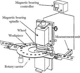
Double-disc grinding is an important process for the ceramics and semiconductor industry and there is interest here to increase accuracy at high-production rates. One vertical spindle machine design reported by Ueda et al. [1998] involves two novelties. The first is the use of live magnetic bearings to control thickness in conjunction with closed-loop gauging. The second, and perhaps more interesting for its simplicity and general application potential, is to increase the grind length by positioning the parts behind the wheel head. This system grinds electronic filters and oscillators to ±0.5 pm.
Although spin and reduced wheel-width techniques cannot be used on majority of doubledisc grinding applications because of fixturing, there is use of it where only a portion of each surface has to be ground. The most active example currently is brake rotor disc. Grinding is carried out as a finishing operation to improve flatness after turning. The rotors are ground on the outer diameter areas, which means they can be readily held and spun in a work holder. In the 1990s, these were ground using conventional wheels or segments [Anon 1996, Thielenhaus n. d.], but more recently these have been replaced by metal-bonded CBN segments [Daisho 2001] or narrow-faced metal-bonded CBN wheels by machine builders such as Thielenhaus and EMAG. The stock amount varies from 5 pm to 100 pm depending on the turning operation and the material (steel or cast iron). Wheel speeds are low at about 25 m/s or less with blocks but up to 60 m/s with thin-rimmed wheels.
|
TABLE 16.11 Examples of Typical Accuracies in Double-Disc Grinding
|
|
|
 |
 |
 Upper wheel


 *4 Carrier Lower wheel