
For manufacturers that choose to rough machine the part, Thielenhaus [n. d.] provides a grinder/superfinisher to microfinish the faces to create a good sealing surface. This is particularly suited for applications such as aluminum cylinder heads with hardened liners that create step problems for machining. The process uses small conventional abrasive segments in a rotating grinding head. Makino [Sess 1999] reported a postmilling process using small high-speed electroplated diamond wheels. A similar combination of turning and electroplated CBN grinding was recently developed to replace double-disc grinding of connecting rods. Three solutions are from machine tool builders with traditions in grinding, superfinishing, and machining, respectively.
16.6.3 SlNGLE-SlDED FACE GRINDING ON SMALL-SURFACE GRINDERS
This particular type of grinding refers to a range of small inexpensive grinders that use wheels from 18 to as small as 6 for a host of small part applications in tool rooms and small production shops. Typical examples include bearing rings, aircraft parts, punches, dies, seals, inserts, pump components, EDM electrodes, and ejector pins. The wheels may be segments, or more commonly continuous rim, and divided between conventional and narrow rim superabrasive grain. In many ways, this is a continuation of the grinding described in the previous section except using smaller, stiffer machines to obtain tighter tolerances, and with an increased wheel speed range on some models up to 10,500 sfpm (55 m/s). Common machine types in the United States include DCM Tech [1999], Swisher [2000], and Delta [1997].
16.6.4 High-Precision Single-Sided Disc Grinding
The grinders referred to in this section are a further extension of those described above focused at flatness tolerances in the micron and submicron level often in competition with lapping.
|
TABLE 16.10 Examples of Face Grinding Applications on Small Rotary Grinders
|
Measurement of flatness at the micron level is critical and care should be taken where flatness has been defined by a machine tool builder as to how that value was determined. Use of indicators on a gauge table, linear measurements on Talysurf-style equipment, or counting fringes using an optical flat and monochromatic light source will generally give an overoptimistic value. The most accurate system currently available for general production is based on various grazing angle reflection interferometry technologies with equipment made by companies such as Tropel and Zygo.
The method relies on the interference of light, and the fact that the reflectivity of a rough surface increases dramatically when the light strikes it at a glancing angle allowing inspection of apparently nonreflective surface such as ceramics, plastics, metals, and composite. It is the same
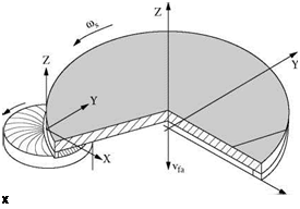 |
FIGURE 16.50 Single-disc grinder configuration.
concept as when sunlight strikes water near sunset. The light is reflected much more than at noon. The system uses a laser beam to generate a well column of light, which is divided into two beams by partial reflection at the prism surface. Part of the beam is then reflected off the part where it is then recombined after re-entering the prism creating interference fringes. A camera system then captures data at about 60,000 coordinate points to compile a 3-D image of the test part. The interference pattern is phase shifted by slightly moving the prism and the sinusoidal variation in light intensity is then monitored for each data point. Software then analyzes the phase shift to give the 3-D height map. The system has a resolution of 0.01 pm, an accuracy of 0.1 pm, and a range of about 30 pm in height variation. Image processing time is about 30 s, which is quite sufficient for shop floor process monitoring. Systems are available to handle up to 500-mm parts.
Single-disc grinder technology for the precision steel industries such as automotive components, hydraulics, seals, etc. has been influenced significantly by developments from the semiconductor industry for wafer grinding. To achieve good flatness requires a very stiff machine combined with precision work handling equipment to hold and spin the part, and low grinding forces. Stiffness is achieved by using small wheels with a large spindle bearing to limit cantilever deflection at the wheel edge. Workholders are belt — or gear-driven to spin the part and narrow-faced wheels are used to limit grinding pressure. This naturally leads to the use of superabrasives for wear considerations.
Koyo [2000], for example, has designed a range of single-disc grinders for targeting parts with flatness requirements of the order of 0.2 to 2.0 pm using several combinations of grind methods, grinding either one or two parts at a time or roughing and finishing simultaneously with two wheel heads. In one instance, the author ground hardened-steel cylinders 25 mm in diameter with vitrified CBN wheels and achieved a flatness of 0.3 pm, finish of 0.15 pm Ra, stock removal of 100 pm in 4-s roughing, and a total production rate of 350/hr dressing every 4,000 parts. This was achieved in water-based coolant.
A similar approach, using narrow-face wheels, has been taken by a number of machine tool builders who traditionally specialized in superfinishing. Their processes now often require stock removal, placing them more into a grinding than a polishing regime. Supfina [1996] has reported a machine design for superfinishing of valve tappets. In this case, the tappet face requires a well — defined crown, which is generated again by the use of a small face wheel but with its axis of rotation tilted slightly to that of the part (Figure 16.52).
Research into the use of superabrasive wheels with narrow face widths has resulted in some surprising developments in production grinding in unexpected areas. If the contact width is kept thin enough, the wheel will maintain its flatness indefinitely resulting in grinders using resin or vitrified CBN that do not require dressers. One example is hob grinding; another is “kiss” grinding of thrustwalls on camshaft and crankshafts as a replacement to turning to improve flatness [Hogan 2001].
|
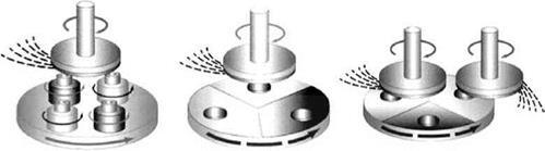
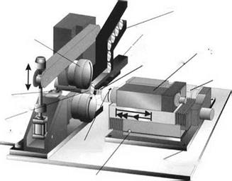
FIGURE 16.51 Grinding strategies for single-disc grinding. (From Koyo 2000. With permission.)
In one example, on crankshafts with Landis 3LB grinders, the author achieved a flatness of <4 pm with a Q of 40 mm3/mm/s and a G-ratio >1,500. The CBN wheels ran at speeds up to 140 m/s in water-based coolant. The flatness could not be achieved by turning because the chip could not be broken without leaving a raised area.