
Face grinding is surface grinding using the face of a grinding wheel. Face grinding may be contrasted with the previous examples in this chapter in which grinding was performed predominantly with the peripheral surface of the grinding wheel. Face grinding encompasses a range of processes characterized by a total conformity between the wheel and workpiece. These include segment grinding, double — and single-disc grinding, and double — and single-sided fine grinding. For such a configuration, the standard equation for uncut chip thickness does not apply since de = «>. Malkin [1989] analyzed vertical spindle face grinding with linear horizontal feed and determined the maximum uncut chip thickness that occurs at the middle of the vertical step (Figure 16.39). For a triangular chip cross section, the chip thickness is given as
where vw = table speed, vs = wheel speed, C is the number of active cutting edges per unit area of the grinding wheel surface, and r is the ratio of width to depth of the triangular chip cross section.
Similarly Malkin [1989] also analyzed face grinding with infeed only (Figure 16.40). In this case, the uncut chip thickness is considered constant and given by
![]()
![]() A Vl
A Vl
Cr’ v
s
where vf = infeed and vs = wheel speed.
FIGURE 16.40 Face-grinding with plunge feed.
For either configuration or in combination, it is, therefore, possible to predict factors affecting grinding energy and power for the process and by implication burn based on
T <x a. v. C.
max e s
Not surprisingly, conventional wheels for surface grinding are open-structure coarse-grit and friable grain. Superabrasive wheels are low concentration to keep Cr values low. Wheel speeds are also reduced or in the case of fine grinding as low at 1 to 3 m/s, in part because of the risk of burn but also because the wheels are in shear, which leads to lower burst speeds than in cylindrical grinding.
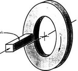
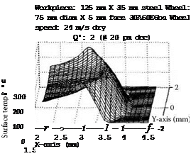
Heat generation and the associated temperature profiles have been modeled for both linear feed and straight infeed grinding. Lin and Zhang [2001] modeled the temperature field for a cup wheel grinding with linear infeed (Figure 16.41).
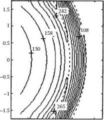
They found that the temperature rise is extremely abrupt at the leading edge of the wheel and does not fall away quickly behind. The rise in temperature peaks within 2 mm of the edge of the wheel. The model is based on a simple arc-line heat source. In reality, there will be frictional rubbing from the flat secondary cutting area leading to additional heating. For this reason, where the grind process allows, such as when using highly wear-resistant superabrasive wheels, the width of contact is kept to less than 5 mm and ideally 3 mm.
Spur [1995] calculated the temperature distribution in solid circular components during doublesided fine grinding. Even at low wheel speeds encountered in fine grinding (<4 m/s) quite significant increases in temperature could arise and be focused at specific points.
 Such temperature distributions cause differential thermal expansion with the effect that more material is ground off the hottest points on the part and flatness is compromised as the part cools. At higher speeds such as in double-disc grinding, especially of thin parts, coolant starvation can create more catastrophic effects akin to film boiling and resulting in severe burning in often quite localized spots. In high-precision grinding or at high speeds, low heat generation and/or effective coolant delivery is critical.
![]()
|
|
 |
|
|
|
![]()
FIGURE 16.41 Temperature distribution in face grinding. (From Lin and Zhang 2001. With permission.)