One of the most fundamental decisions for the process engineer is to decide which is the most suitable metal removal process. For example, EDM is a relatively slow method for cutting complex forms but
|
|
||
|
|||
|
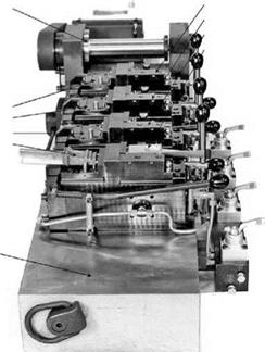

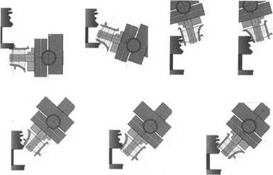
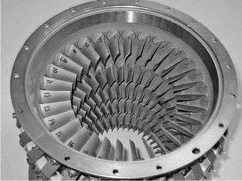
FIGURE 16.28 Parts ganged up in series.
 |
EDM machines are inexpensive relative to a grinder. Therefore it may be less expensive and more flexible to buy several EDM machines than a single grinder. The decision must be based on capital equipment costs, cycle times, wire/abrasive costs, and tolerances. Milling of nickel-based alloys is very expensive in perishable tooling costs, and with advances in CBN and ceramic wheel technology, manufacturers of land-based engine components are beginning to convert to grinding (Figure 16.32).
|
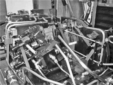
FIGURE 16.30 Hard-point mounting fixture for nozzle guide vane. |
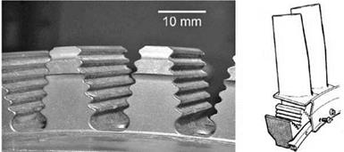
Grinding is also being considered as a replacement for broaching of nickel alloys again due to the high capital and tooling costs, long tool change times, high broaching forces, and floor space required. Burrows et al. [2002] and Aspinall et al. [2002], for example, reported on a study for a consortium including Rolls Royce and SNECMA to replace the broaching of turbine compressor disc root forms with grinding; the root form being first rough ground with Altos wheels then finished ground using small profiled plated CBN pins (Figure 16.33).
|
|
|
FIGURE 16.32 Multiaxis machining center for grinding land-based gas turbine buckets with plated CBN wheels to replace milling and HSK automatic wheel changing. |
It is interesting to note this study was carried out using a vertical machining center and made significant reference to “multitasking.” The move to multisurface processing of parts in one fixture has demonstrated the benefits in terms of improved tolerances from processing components in a single clamping. However, there is no reason why each metal removal operation must be one of grinding. In multitasking, a machine may be required to do several operations including grind, mill, turn, probe, burnish, and deburr. Machine tools now become much more generic with companies traditionally involved with machining centers offering grinding capability, while manufacturers of grinding machining
|
|
 Cooled
spindle
lubricant
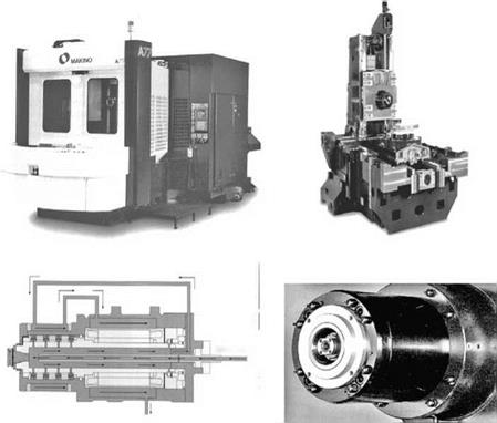
FIGURE 16.34 Makino A77 grinding center and components.
offer options common to machining centers such as quick-change HSK tooling, milling, and turning capabilities, and a radically different working volume in terms of machine axes movement and reach.
Several of the large manufacturers of high performance machining centers now promote “grinding centers”—machines with structural, drive, and control components, coolant delivery systems, and size control ability comparable or superior to many grinders. On the other hand, manufacturers of high-speed grinders such as Edgetek now refer to their processing as “abrasive machining.” The distinction between a grinding machine and a machining center has become blurred in these instances.
The natural conclusion to this trend is for some end users to attempt to further reduce capital equipment costs by the use of low-cost, mass-produced, vertical machining centers (VMCs) and making modifications to them in-house typically to run plated CBN wheels. This approach has met with some success in application with noncritical tolerances, but the end user should be aware that the stiffness, thermal stability, and repeatability may not be in the same class as a modern grinder and savings in capital equipment may be lost in process development with no guarantee of success as very few VMC manufacturers provide turnkey processes. Attention must also be paid to differences in guarding codes.
With so many options and new technologies to choose from, the selection of the best is difficult. At the current time, the following approaches are being taken by manufacturing: [7]
 |
 |
technology in water-based coolant, or advance ceramic grain wheels in water or oil coolant. The shift to hard-point mounting is slower in these cases because of the higher forces imparted by the higher removal rates that in turn cause part deflection. This is especially a problem when the reference mount points are on thin aerofoil sections.
• Job shop and small-batch manufacturers willing to grind in oil coolant are using predominantly plated CBN with some advanced ceramic grain wheels on simpler form or flat surfaces.
• Job shop and small-batch manufacturers: those unwilling to grind in oil coolant use a combination of conventional alox wheels with CDCF, plated CBN for radial grooves, and occasional vitrified CBN usage as volume justifies.
• Heavy stock castings for land-based engines: manufacturers are moving away from milling to grinding in oil with a combination of advanced ceramic grain (Altos) wheels for roughing and plated CBN for finishing. Existing grind applications with heavy stock on older equipment remain with CDCF technology.
|
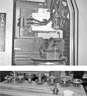
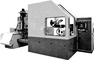
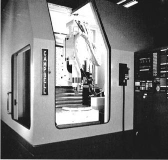
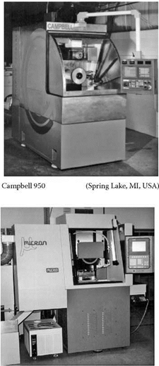
FIGURE 16.36 Example of 5-axis horizontal spindle grinder for aircraft engine blade multisurface grinding. (Courtesy of Campbell Grinder. With permission.) |
Recent developments in machine design have progressed hand-in-glove with the changes occurring in part processing. Dedicated machines for vitrified CBN use small wheels in the range of 8 to 12 (200 to 300 mm) to minimize wheel cost while still maintaining an acceptable range for the dressing crush ratio across a typical 1 depth of form profile.
The working area within the machine is now more a cube to accept the bulky work holding fixture but give free access in all directions. In many cases, this allows a complete downsizing of
|
|
 |
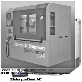
the machine size, especially width, but with increased stiffness. Several machine tool builders of small, mini, creep feed grinders report machine loop stiffness values in the range of 750,000 to 1,250,000 lbf/in. (130 to 220 N/pm).
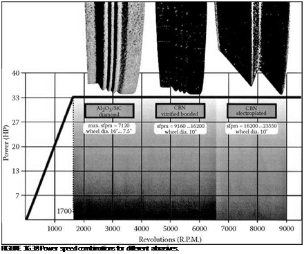
Wheel spindle motors must be variable speed with power and torque curve characteristics closely matched to the expected wheel diameter range and types of wheels to be run. This ensures sufficient power over the full life and expected operating speeds of each wheel type. Most ac servomotors have a peak power at a particular rpm and drop off progressively with rpm on either side of this value. Trying to combine different wheel types and diameters, therefore, becomes a compromise. The required wheel speed ranges and diameters for each wheel type are normally as shown in Table 16.9.
It is possible to provide flexibility in order to use a combination of vitrified CBN and regular alox wheels or to use vitrified and plated CBN. In order to provide flexibility with a single machine configuration for all three compromises the power available, some OEMs, such as Blohm [n. d.],
![]()
![]()
![]()
 |
|
Wheel Diameters against Operating Speed
|
have developed their spindle technology (Figure 16.39) to extend the range of RPMs over which they can maintain a high level of power. This makes their grinders particularly suitable for the job shop environment by now allowing the use of all the three abrasive types without significant compromise on wheel diameters.
In conclusion, the machine tool industry has undergone major changes over the last 5 years driven by changes in part-processing philosophy and abrasive-wheel technology. This has led at one extreme to dedicated grinders designed in many cases to the processing of a specific part. At the other extreme, machine tools have become ever more flexible both in the use of a greater range of wheel technologies and to encompass multiple metal removal processes.

