
Electroplated CBN wheels consist of a single layer of CBN crystals on a profiled metal hub. As discussed in Chapter 4, this leads to limits on finish and profile tolerances unless the surface is conditioned after plating which adds significantly to the cost. Therefore, the wheels are used more typically in roughing operations and under conditions that maximize life, namely, high wheel speed and oil coolant.
The impact of oil on wheel life cannot be understated. Gaulin [2002] reports a typical life difference between grinding in oil and grinding in water-based coolant of 100:1. Certainly while grinding nickel-based alloys, the author has observed very repeatable data showing 25 to 75 times more life with a good mineral oil compared to the latest synthetic or semisynthetic water-based coolant. Complicated profiles with tight radius requirements may reduce the benefits of oil to some degree, but the improvement relative to water-based coolants is still extreme. In fact, the impact on life is so extreme that the economic use of plated CBN in water-based coolants, certainly as far as the aircraft engine industry is concerned, is very questionable except for small job lots where manufacturing must weigh the wheel cost against the cost of buying expensive formed diamond rolls to dress a bonded wheel and the equipment to utilize them.
The impact of high wheel speed is very similar to that discussed under external cylindrical grinding especially with operation under high efficiency deep grinding (HEDG) conditions. The biggest benefits of plated CBN in HEDG grinding comes about by achieving high stock-removal rates with deep depths of cut and low U’ values while maintaining a modest overall grinding power to keep forces within the range of normal machine stiffness. Not surprisingly, the typical examples seen in the trade literature are narrow slots in, for example, collets, spanners, and pump rotors.
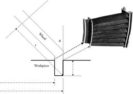
There is one particular application for electroplated CBN wheels that has been the driver for machine design to do HEDG grinding, and that is radial groove grinding of aeroengine components. Many engine components, for example, vanes, nozzles, and casings, require narrow radial slots to be machines in them. Most engines are 500 to 1,000 mm in diameter, which sets the typical range of the slot diameters. Traditionally, these would either be milled with a very small diameter cutter, which is very expensive, or plunge ground with a 2A2 plated wheel of the same diameter as the groove. A 1,000-mm-diameter plated CBN wheel is also both expensive and requires a massive machine to utilize it. An alternative approach is to grind the slot with a small cup wheel of a very precise diameter and dish angle. Figure 16.21 shows the configuration. The groove of depth d has inner and outer faces defined by radii R1 and R2, respectively. The cup wheel or radius r is tilted 0° from the vertical. The critical part tolerance is usually the outer groove face taper, which must be held to a tolerance of <5 pm. By comparison, the overall groove width has a tolerance of typically 50 to 100 pm. Simple geometry calculation shows that for a part outer radius, R2, the maximum wheel radius to give a theoretical vertical face is given by r = R2Sin. Applying this value of 0 to the inner wall radius, Rj, gives a radial difference (taper) between top and bottom of the groove of
AR1 = d2(1 + Sin 20) R >> AR r = R2Sin0 2R1Cos20 R2 > R1
If the component tolerancing does not define an outer groove face taper but merely the overall taper from top to bottom of the groove, it is possible to further improve the overall taper by reducing 0 about n °. It should be noted that AR1 increases as d2 but for small changes in angle reducing 0 produces only a linear relationship of AR2 with d. The final adjustment of 0 is usually done using a 3D CAD design program such as Unigraphics.
 d
d
Inner groove wall radius Rj
Outer groove wall radius R2
FIGURE 16.21 Configuration for radial groove grinding using plated CBN wheels.
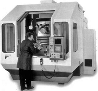
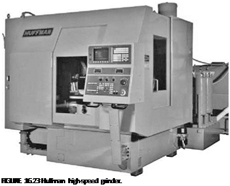
в usually lies in the range of 10° to 20° which defines the wheel diameter in the range of 125 mm to 250 mm. This, in turn, defines the wheel capacity of the machine. Furthermore, the interpolation of the radius requires the coordinated movement of several axes. This has led to purpose-designed grinders such as the Edgetek HEDG grinder (Holroyd Machines, U. K.) (Figure 16.22), but also the adaption of advanced tool and cutter grinders capable of complex, accurate CNC path movements. An example of this from Huffman (Clover, SC) is shown in Figure 16.23.
|
|
Under ideal conditions with deep depths of cut, oil coolant, and high wheel speeds, plated wheels can achieve Q = 100 to 2,000 depending on the material grindability. However, as with CDCF, conditions are rarely ideal and stock removal rates may be only 10% of those indicated above. For example, grinding Inconel 718 or similar, the maximum stock removal rate in the majority of applications based on burn and wheel life considerations is <8 mm3/mm/s.