Coolant must be delivered from the pump via the piping, valves, and nozzle at the required pressure to match wheel velocity and in a laminar flow. Any turbulence or entrained air will create dispersion
|
TABLE 16.4 Metric Flowrate Chart for a Nozzle with a Coefficient of Discharge of 0.95 Flowrate (1/min) for Listed Nozzle Diameters (mm) Coolant Nozzle Pressure (Bar) and Areas (mm2)
|
|
Speed |
Water |
Mineral Oil |
Ester Oil |
.003 |
.012 |
.028 |
.049 |
.077 |
.11 |
.15 |
.196 |
Area |
|
(fpm) |
SG = 1.0 |
SG = 0.87 |
SG = 0.93 |
1/16 |
1/8 |
3/16 |
1/4 |
5/16 |
3/8 |
7/17 |
1/2 |
Diam. |
|
4,000 |
30 |
26 |
28 |
0.6 |
2.4 |
5.5 |
9.7 |
15 |
22 |
30 |
39 |
|
|
6,000 |
67 |
58 |
62 |
0.9 |
3.6 |
8.2 |
15 |
23 |
33 |
45 |
58 |
|
|
8,000 |
119 |
104 |
111 |
1.2 |
4.8 |
11 |
19 |
30 |
44 |
59 |
78 |
|
|
10,000 |
187 |
163 |
174 |
1.5 |
6.1 |
14 |
24 |
38 |
55 |
74 |
97 |
|
|
12,000 |
269 |
234 |
250 |
1.8 |
7.3 |
16 |
29 |
45 |
65 |
89 |
116 |
|
|
14,000 |
366 |
318 |
340 |
2.1 |
8.5 |
19 |
34 |
53 |
76 |
104 |
136 |
|
|
16,000 |
478 |
416 |
445 |
2.4 |
9.7 |
22 |
39 |
61 |
87 |
119 |
155 |
|
|
18,000 |
605 |
526 |
563 |
2.7 |
11 |
25 |
44 |
68 |
98 |
134 |
174 |
|
|
20,000 |
747 |
650 |
695 |
3.0 |
12 |
27 |
48 |
76 |
109 |
148 |
194 |
|
|
25,000 |
1,166 |
1,014 |
1,084 |
3.8 |
15 |
34 |
61 |
95 |
136 |
185 |
242 |
|
|
30,000 |
1,680 |
1,462 |
1,562 |
4.5 |
18 |
41 |
73 |
114 |
164 |
223 |
291 |
|
|
35,000 |
2,286 |
1,989 |
2,126 |
5.3 |
21 |
48 |
85 |
132 |
191 |
260 |
339 |
|
|
40,000 |
2,986 |
2,598 |
2,777 |
6.1 |
24 |
55 |
97 |
151 |
218 |
297 |
388 |
|
TABLE 16.5 English Flowrate Chart for a Nozzle with a Coefficient of Discharge of 0.95 Flowrate (GPM) for Listed Nozzle Diameters (in.) and |
|
Coolant Nozzle Pressure (psi) Areas (in.2) |
causing a rapid loss of momentum and preventing the coolant from overcoming the momentum of air generated by wheel drag—the so-called “air barrier.”
Turbulence can be an inherent problem of the system governed by its Reynolds number (Re), which is defined as:
where
v = fluid velocity d = diameter of jet or pipe
v = kinematic viscosity of fluid (10-6 m2/s for water)
The Reynolds number is a measure of flow quality where smaller is less turbulent. Coolant jets are always turbulent. Laminar coolant supply nozzles are rare. Re values in excess of about 2,000 will have turbulence; a value that encompasses virtually all grinding situations. Nevertheless, values up to 100,000 can still give a reasonably constrained flow. The Re value should be improved where possible by chilling the coolant to increase viscosity or by reducing the exit diameter by using several small nozzles. Turbulence and pressure losses can also be generated within the pipes by bends, changes in pipe diameter, or rough surfaces. This can be eliminated
|
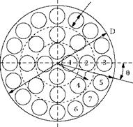
TABLE 16.6 Maximum Flowrates for 6 m/s Velocity
|
|
|
|
|
|
# |
1 |
2 |
3 |
4 |
5 |
6 |
7 |
|
0 |
0 |
0 |
0 |
45.0 |
22.5 |
67.5 |
45.0 |
|
r |
.109D |
.258D |
.414D |
.258D |
.414D |
.414D |
.414D |
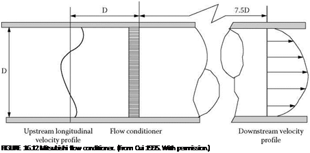
by the use of a flow conditioner just prior to the nozzle system. One very simple style proposed by Webster consists of a Mitsubishi inline flow conditioner, originally designed for creating laminar flow in systems to measure city water supplies as shown in Figure 16.12 Its most important feature is the ability to present a laminar flow to the nozzle entrance with virtually zero drop in pressure.
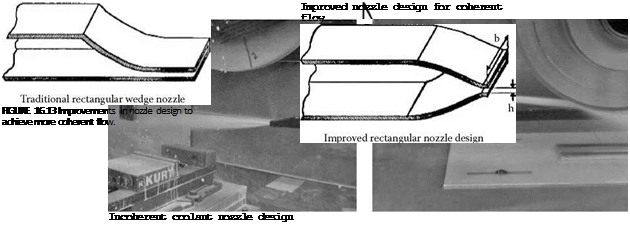
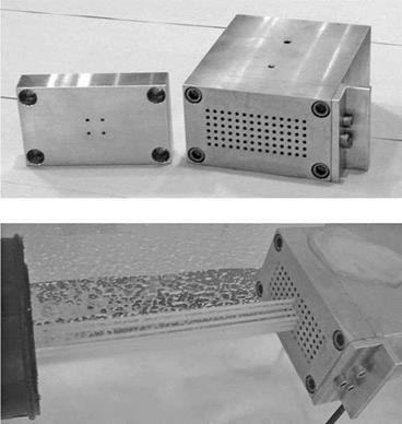
An optimized nozzle design is as simple as it is effective. The design developed by Webster, Cui, and Mindek at the University of Connecticut to generate coherent jets was based on the 1950 fire hose technology. The beauty of the design is the way it balances all the forces from the coolant such that at the exit all flow is perpendicular to the exit. Ideally this balance is best maintained by using a round opening. However, the design is almost as efficient with a rectangular opening except for some small dispersion effects at the corners as long as the internal profile is balanced (Figure 16.13).
Complex-shaped exit designs to follow the form of the wheel profile should be avoided as they are generally highly dispersing. Instead, several smaller round nozzles can be used far more effectively. When building the nozzles, care should be taken to make sure the inner surface is as smooth as possible and that a sharp edge is maintained at the exit (no nicks).
The concept of using small, round nozzle exits has been taken one stage further by a patented “card key” system whereby quick-change nozzle plates carrying several small, round, internally contoured exits for each required wheel profile can be placed inside a plenum chamber. The system is offered as part of the Field Services Program at Higgins Grinding Technology Center (HGTC), Worcester (Saint-Gobain Abrasives) (Figure 16.14).
Oil coolant has a higher viscosity than water making jet coherency a lot easier. It also offers great benefits in terms of abrasive life (up to 100 x with plated CBN!). However, oil has a range of problems of its own. It is potentially a hazard both environmentally from misting and as a fire risk. It also has a half to a quarter of the thermal conductivity and heat capacity, and is more prone to air entrapment. Gaulin [2002] infers the following coolant system requirements for oil:
![]()
1 gpm/wheel spindle hp 25 min
4,000 BTU/wheel spindle hp
|
FIGURE 16.14 Plenum chamber coolant delivery with quick change “card key” nozzle plates. (Courtesy of Saint-Gobain Abrasives. With permission.) |
Although the flowrates are actually lower than those for water-based coolant, the settling time and chiller capacity are both approximately triple. The risk of fire is real although somewhat exaggerated. Every oil coolant has a lower and upper explosion limit based on the percentage of oil to air. The limits are typically 0.6% to 7% by volume of oil when the oil can actually be ignited. Flushing the grind area well or throwing down a curtain of oil to flood and knock down misting greatly reduces the fire risk. In the event of a fire there is an overpressure created in the grinder of about 4.5 bar max. So grinders equipped for handling oil should have:
• Good encapsulation to prevent oil or mist from exiting
• An efficient mist extraction system
• A CO2 fire suppression system
• A spring-loaded flap to release the initial pressure generated from an explosion
• Automatically seal as the CO2 system kicks in
It is interesting to note that a survey carried out in Germany between 1987 and 1994 found the leading causes of fire were [Ott and Storr 2001] [5]
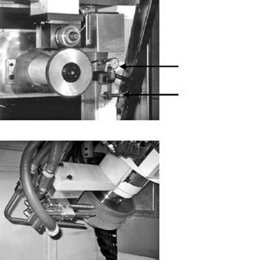 Single nozzle arrangement for creep feed grinding of jet engine blade dovetail
Pressure gauge
Single fire hose round nozzle
Multiple fire hose round nozzle arrangement for wide form application
FIGURE 16.15 Examples of fire hose round nozzle applications.
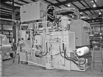
The impact of oil on the physical size of a coolant can be seen from Figure 16.16. This illustrates a self-contained, compact coolant system designed for a single grinder with a 40 Hp (30 KW) spindle and plated CBN wheels. It consists of a 280 psi (20 bar), 60 gpm (225 l/min) high volume pump, a 1,000 psi (70 bar), 5 gpm (19 l/min) high-pressure scrubber pump, vacuum paper filtration unit, chiller, air-extraction unit, and a coolant tank large enough to allow a 15 min settling time. The system is actually larger than many of the grinders it is designed to supply.
Coolant delivery to creep feed grinding is also a consideration when examining the importance of up — versus down-grinding.
To re-emphasize comments made before, in up-cut grinding, each individual grit experiences a high proportion of its time in contact initially just rubbing or ploughing the workpiece material. This consumes a large amount of energy in friction and elastic and plastic deformation. Only as the grit reaches its exit point does it make a sufficiently deep cutting depth to initiate a chip. In down-cut grinding the chip is almost immediately created suppressing many of the friction losses. In up-grinding the coolant introduced at the point of entry of the wheel acts directly on the newly formed surface. In down-grinding, coolant again added at the point of entry of the wheel must be carried through the grind zone, during which it is heated up before it can react with the newly produced surface [Tawakoli 1993]. In actual production situations, the ease of effectively introducing coolant into the grind for a down-cut grind configuration appears to far outweigh any advantages of the kinematics of up-grinding.
In summary, there are lower grinding forces and power, and a lower risk of burning in downgrinding. Up-grinding, although able on occasion to give longer life, should be reserved for just the last pass in a finish grind mode at <50 pm d. o.c. and relatively high-table speed to help remove artifacts from the rough grind such as burrs and edge faceting produced by the influence of coolant hydrodynamic force changes.
|
FIGURE 16.16 Oil coolant system for use with a 40-Hp grinder operating with plated CBN wheels (pumps, chiller, filter, settling tank, and mist collection). (Courtesy of Campbell Grinders, Spring Lake, MI. With permission.) |