
Since coolant is such a key factor in continuous dressing (CD) grinding, close attention must be paid to all aspects of the coolant delivery system. Most creep feed applications either have
|
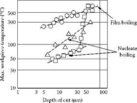
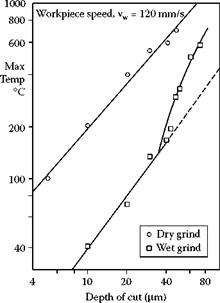
FIGURE 16.10 Illustrations of the impact that film boiling has on workpiece surface temperatures. (From Howes 1990, 1991. With permission.)
 |
interference with fixtures or other issues that prevent an efficient shoe nozzle from being used. Therefore, coolant delivery must depend on coherent flow nozzle design with sufficient coolant volume and pressure. This discussion is valid for any grind operation where shoe style nozzles cannot be used. Extensive research and consolidation of available information on this subject
carried out by Webster is included in the summary below [Webster, Cui, and Mindek 1995, Webster 2000, Webster et al. 2002].
16.5.2.2.1 Coolant System Capacity
The standard coolant requirement is 1.5 to 2 gpm/hp of grinding power. A good estimation for minimum flowrate is therefore to take the spindle horsepower x 1.5 gpm. For a water-based coolant, at least 10 min is required for settling to allow the release of entrapped air and minimize foaming. This then defines the tank capacity requirement.
16.5.2.2.2 Coolant Pressure
The optimized coolant pressure at the nozzle is such that the coolant velocity matches the wheel velocity. The coolant velocity can be readily calculated from the coolant pressure using V = (2AP/p)1/2, where V is coolant velocity, AP is the pressure, and p is the coolant density. Note that calculating the velocity based on the flowrate and the cross-sectional area of the nozzle aperture will always underestimate the velocity as the actual coolant jet cross-sectional area may constrict upon exit depending on the nozzle design. It is always best to measure the pressure as close to the nozzle as possible. With that caveat, Table 16.4 and Table 16.5 give the velocity as a function of pressure together with the associated maximum flow rates for various aperture cross-sectional areas.
16.5.2.2.3 Piping
Values are given in Table 16.6 of pipe diameter against pressure and flowrate. Pressure is to be specified at the nozzle, not at the pump. Piping should be kept as short as possible with minimal bends to avoid head losses. The pipe diameter should also be made as large both to lower head losses but also to keep the flow in the laminar. Webster recommends a velocity of 6 m/s max to keep the Reynolds number of a water-based fluid below the level causing turbulence. This gives the following maximum flowrates for given pipe diameters.