
An innovation of surface grinding driven by the Japanese in the 1980s is a process called Speed Stroke Grinding that involves very high table speeds of 50 to 100 m/min and shallow depth of cuts of the order of 1 pm or less. The interest was initially centered around improved die manufacture and achieving high stock removal rates grinding ceramics while keeping the depth of cut in the ductile grind regime. The earliest work was carried out on Elb grinders using toothed belt drives [Yuji 1990] and on Okamoto grinders [Akinori 1992]. High helix pitch ballscrews and, more recently, the introduction of linear motors have greatly expanded the scope in terms of speed, and acceleration and deceleration rates.
The benefits and drawbacks of the process can be understood by going back to the basic equations relating uncut chip thickness, hcu, to specific grinding energy, ec, force/grit, fg, surface finish, Rt , and mean surface temperature (0):
For a constant stock removal rate, chip thickness increases with workspeed. Consequently, specific energy decreases as table speed increases for constant removal rate, depth of cut, and surface temperature fall, while surface roughness increases and force/grit increases.
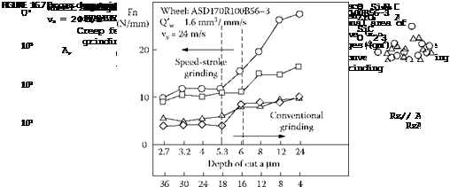 |
Speed-stroke grinding, therefore, offers the ability to remove stock faster and with lower forces and less risk of burn, but roughness will be higher and compensation must be made in bond/grit strength for increased force/grit. (Compensation for higher roughness can be made by controlling the process; i. e., switching to a slow table speed for finish grinding). These predictions were demonstrated by Inasaki [1988] in the grinding of alumina and zirconia with resin diamond wheels on a lead screw-driven machine at up to 36 m/min (Figure 16.7).
For the machine tool builder, the primary area of concern for machine design is being able to control the acceleration and deceleration rates without excessive vibration and without overshooting the part so much that the benefits of cycle time are lost (Figure 16.8).
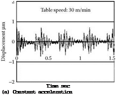
The big advantage of the linear motor is that the pattern of the acceleration and deceleration can be readily adjusted so that forced vibrations can be minimized. Inasaki [1999], for example, demonstrated that a sinusoidal pattern for acceleration and deceleration can successfully suppress wheel head vibration (Figure 16.9).
Wheel grade selection is severely impacted by the effective high level of interrupted cut and high force/grit. Tonshoff, Meyer, and Wobker [1996] reported that wheel wear during speed stroke grinding of alumina was very dependent on bond type. Electroplated and resin bonds showed little
![]()
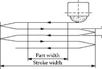
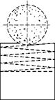
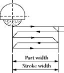
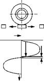
FIGURE 16.8 Strategies for velocity profiles for speed-stroke grinding.
wear, but metal-bonded wheel wear was significant and vitrified bond wheel wear was dramatic. The differences in wheel wear were postulated to be due to the relative brittleness of the bond in the presence of vibration.
The Jung S320 was one of the first grinders to be offered commercially for speed-stroke grinding targeted at nonstandard punch grinding, slot grinding, and tooling prone to vibration [Motion 2001]. The grinder had a linear motor drive offering 50 m/min at 600 strokes/min and an X-axis position accuracy of 3 pm on 15-mm stroke length.
 |
|||
Danobat designed a machine capable of 200 m/min and a maximum accelerating/decelerating rate of 3 g [Hitchiner 2005]. Speed-stroke grinding is expected to grow in numerous industries as original equipment manufacturers (OEMs) become more experienced in the use of linear magnetic motors.