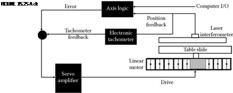
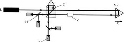
Linear motors demand fast positional monitoring response made possible by using linear encoders based on laser interferometry. The simplest form using a homodyne laser is illustrated in Figure 15.27. A laser beam, L, is split by a neutral beam splitter, N, into two beams. The measuring beam strikes the measuring reflector, MR, which is returned in a parallel path where it passes through a Я/4 reticule, V, where a portion of the beam is delayed to create a circularly polarized wave. The reference beam is reflected by the reference reflector such that the two beams meet again at the neutral beam splitter and interfere. Further polarizing beam splitters, PT, put the interfering waves into quadrature measured by the four photodiodes, P, resulting in two electrical signals phase shifted by 90°. These signals are then converted into two square wave signals with eight crossover
![]()
 |
Armature
(slider)
Magnetic track
Linear guide
Linear encoder
FIGURE 15.26 Elements of a linear motor drive system.
|
RR
FIGURE 15.27 Principle of the laser interferometer. (From Ernst 1998. With permission.) |
points per wavelength of light giving an accuracy of about 0.08 pm. An interpolation circuit can increase sensitivity by a further order of magnitude.
Heterodyne laser systems are also available that use two almost identical wavelengths. Compensation is also possible for temperature, humidity, and air pressure. Fortunately, the clean conditions required for linear motor operation also make conditions unusually suitable for a grinder application and for laser interferometers.

