
Ac servomotors are a class of induction motor modified for servo-operation. It is an asynchronous motor consisting of a stationary ac transformer (stator) and a rotating shorted secondary circuit (rotor) that carries an induced secondary current. The rotor consists of laminated iron cores with slots for conductors. Torque is produced by the interaction of the moving magnetic field and the induced current in the shorted conductors. In a simple induction motor, the speed at which the magnetic field rotates is the synchronous speed of the motor and is determined by the number of poles in the stator and the frequency of the power supply. For servomotor operation, the stator is wound with two phases (or four) at right angles. The first winding has a fixed voltage supply while the second has an adjustable voltage controlled by a servoamplifier. The great attraction of the motor is its accurate and rapid response characteristics. The motors are available in fractional and integral horsepower sizes and are used in a closed-loop control system in which energy is the control variable. In order to monitor this, the controller must be able to constantly monitor velocity and position. This is achieved through the use of encoders.
15.8.4 Encoders
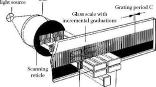
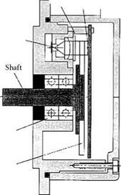
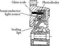
Encoders monitor position and rotation and their derivatives, speed, acceleration, etc. The leading manufacturer is Heidenhain, on whose literature most of this discussion is based [Ernst 1998]. The simplest and most common encoders are rotary encoders mounted directly on the back of the servomotor to monitor the rotation position. The encoder functions on the Moire principle. The system uses a glass scale or disc because of its transparency and low thermal expansion. The scale has a grating, produced by photolithography, of fine opaque chromium lines of thickness C/2 and spacing C.
The grating is scanned using a reticule with four windows illuminated by collimated light source. Each window has similar grating lines parallel to the scale. The light passing through each window and the scale is measured by its own photodiode behind.
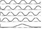
As the scale moves relative to the windows, a sinusoidal light intensity is produced that is converted to an electrical current. The signal from the four windows is each phase shifted 90°, signal (a) to signal (d) in Figure 15.24. Signal (e) is a reference. Signal (a) and signal (c), and signal (b) and signal (d) are then combined to produce the balanced amplitude signals S1 and S2, which are converted to square wave signal (h) and signal (i). Combination of signal (h) and signal (i) gives a final pulse with a resolution of one fourth of the grating spacing. Further resolution can be obtained via an interpolation circuit. The output is typically 1 V peak to peak.
Rotary encoders can have up to 5,000 radial lines giving 20,000 measuring points per revolution. For a ballscrew pitch of 10 mm this gives a resolution of 0.5 pm. Better resolution can be obtained with interpolation. Rotary encoders function at signal frequencies of 160 kHz to 400 kHz. At 400 kHz with 5000 lines, the maximum table speed allowed corresponds to 400,000/5000 = 80 rev/s giving 48 m/min. This speed is acceptable for all normal grinding operations and even some speed stroke grinding applications. Gratings with up to 36,000 lines are available for purely angular positioning. Rotary encoders are also available that have several graduated disks linked by a mechanical transmission that allows them to resolve the number of spindle revolutions and, therefore, the absolute slide position. This negates the need for limit and reference switches but at some loss of resolution.
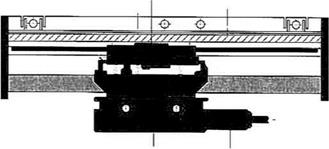
Rotary encoders are as good if not better at giving feedback on velocity as a tachometer but they are sometimes too remote from the point of grinding to accurately know the position of a slide where it matters. The machine may be too sensitive to thermal variations especially for the resolution required for some high precision applications or the use of CBN. For this reason glass, linear scales are placed next to the slides for positional reading with feedback direct to the programmable multiaxis controller (PMAC). In many cases, if the material for the scale carrier has the same expansion as the workpiece, the thermal effects of the scale and workpiece compensate each other. A standard linear encoder with a period of 20 pm has accuracy of the order of 3 pm/m. As such, this allows measuring steps of 0.5 to 1 pm.
The units come “sealed” but nevertheless they should be carefully guarded from coolant and contamination. It is common to mount them under the same slideway guards used to protect the linear guides.
|
|
||
|
|||
|
|||
|
|||
|
|||
|
|||
|
|||
|
|||
|
|||
|
|||
|
|||
|
|||
|
![]()
15.8.5 Resolvers
Machines built prior to about 1990 may have a resolver, in place of an encoder, based on the inductive measuring principle or “Inductosyn.” In this case a scale and slider consist of two staggered or zigzag conductive strips. An alternating current is passed through the slider and the inductive current measured in the scale circuit. Resolvers of this type are much less accurate than modern encoders and more sensitive to temperature changes.