
In almost all grinding processes, coolants are used to reduce heat and to provide sufficient lubrication. These are the main functions of any coolant supply. Furthermore, the removal of chips and process residues from the workspace of the machine tool, the protection of surfaces, and human compatibility should be provided. Modern coolant compositions also try to fulfill the contradictory demands of long-term stability and biological recycling ability.
With the wider use of superabrasives such as CBN and the possibility of high-speed grinding and high-efficiency deep grinding, more attention has been paid to the coolant supply. Coolant pressure and flow rate measured with a simple flowmeter in the coolant supply tube before the nozzle are often part of the parameter descriptions. Different authors have also worked on the influence of different nozzle designs [e. g., Heuer 1992]. In most cases, the influence of different supply options including conventional flooding nozzles, shoe, spot jet, or spray nozzles or even
 Backflow and foam


![]()
![]()
![]()
![]()
 Qcl =
Qcl =
20 l/min
internal supply through the grinding wheel is described by using the previously mentioned process quantities such as forces or temperature [Heinzel 1999].
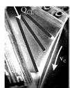
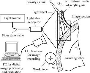
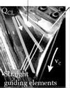
Besides the technological demands, the environmental aspects of manufacturing get significantly more attention. The last mentioned point especially has led attention toward a detailed investigation of coolant supply and the possibility to reduce or avoid coolants in grinding completely [Karpuschewski, Brunner, and Falkenburg 1997]. Brinksmeier, Heinzel, and Wittmann [1999] and Heinzel [1999] made a very systematic approach to investigate the coolant-related influences and to optimize the relevant parameters and designs. A special flow-visualization technique was used for the development of a suitable shoe nozzle design (Figure 11.27). Tracer particles with almost the same density are added to the transparent fluid. All interesting parts of the nozzle are made from acrylic glass and a CCD-camera is recording the flow images perpendicular to the light sheet plane. Although only a qualitative result is available, this technique offers the possibility to systematically study and improve the whole design of coolant nozzles. As an example, Figure 11.27 (right) shows the flow behavior of a nozzle with straight guiding elements at two different flowrates.
The coolant is mineral oil and the grinding wheel is rotating at a speed of 100 m/s. For the smaller flowrate of 10 l/min, inhomogeneous flow behavior can be observed. Turbulences, backflow, and foam between top — and center-guiding elements and at the entry side of the grinding wheel are visible. A doubling of the flowrate leads to steady flow behavior.
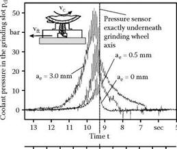
Besides this use of an optical monitoring method to optimize the design of coolant nozzles, a special sensor installation for pressure and force investigations was introduced [Heinzel 1999]. The force measurement is done by an already-discussed piezoelectric dynamometer. During grinding, only the total normal force can be registered by this instrument. The idea is to separate the normal force component used for cutting, friction, and deformation from the component that is resulting from the buildup of the hydrostatic pressure between grinding wheel and workpiece, and because of the impact of the coolant flow on the surfaces. For this purpose, an additional pressure sensor is integrated in the workpiece carrier, allowing measurement of the pressure course over a grinding path through a bore in the workpiece. In Figure 11.28 results of this sensor configuration are shown [Heinzel 1999].
The left part shows a result of the pressure measurement in dependence of different depths of cut. It is shown that with increasing infeed the maximum of the pressure distribution is shifted in
Effective width of pressure zone: 4yeff = 3.32 mm Workpiece: 100Cr6, 62 HRC Length: 100 mm, width: 10 mm 700
![]()
![]()

![]()
![]()
![]()
 N
N
a
500
и
5-і
400
я
![]() а
а
![]() 300 с
300 с
200 H
![]()
![]() 100
100
0
front of the contact zone, which can be explained by the geometry of the generated slot. Higher infeed leads to a geometrical boundary in front of the contact zone and results in a rise of the dynamic pressure. If the measured pressure distribution is numerically integrated over the corresponding workpiece surface, the coolant pressure force component can be determined taking some assumptions for the calculation into consideration.
The right side of Figure 11.28 shows results of this combined calculation and measurement. A path with no infeed is already leading to a normal force of 34 N, only generated by the coolant pressure. With increasing depth of cut the amount of this force component is, of course, reduced. Almost half of the normal force is attributed to the coolant pressure, even under deep grinding conditions of ae = 3 mm.
This described method is suitable to investigate the influence of different coolant compositions. The efficiency of additives can be evaluated especially if the coolant pressure force component is known and can be subtracted from the total normal force to emphasize the effect on the cutting, friction, and deformation component.
The use of special sensor systems for coolant-supply investigations is a relative new field of activities. First results have shown that these sensors can contribute to a better understanding of the complex thermomechanical interaction in the zone of contact. Also, direct industrial improvements such as coolant nozzle optimization or additive efficiency evaluations for grinding can be performed. Thus a further improvement of the monitoring techniques is desirable.