
All the mentioned restrictions of contacting sensor systems on the workpiece surface gave a significant push to develop noncontact sensors. As for grinding wheels again, optical systems seem to have a high potential. In Figure 11.22, different optical systems as well as two other noncontacting sensor principles are introduced.
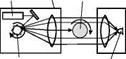
A laser-scanner is shown as a very fast optical system to measure macrogeometrical quantities. The scanner transmitter contains primarily the beam-emitting HeNe-laser, a rotating polygonal mirror, and a collimating lens for paralleling the diffused-laser beam. The setup of the scanner receiver contains a collective lens and a photo diode. The electronic evaluation unit counts the time, and the photo diode
Optical sensors


![]()
![]()
![]()

![]()
![]()
 Compact sensor unit
GaAs-
 |
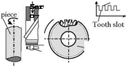 |
Photo diode array
FIGURE 11.22 Noncontact sensor systems for workpiece quality characterization.
is covered by the shadow of the object. The diameter is a function of the speed of the polygonal mirror and the time the laser beam does not reach the covered photo diode. Conicity can be evaluated by an axial shifting of the workpiece. On principle, this optical measurement cannot be performed during the application of coolant. For a detailed workpiece characterization, a setup with a laser-scanner outside of the working space of the grinding machine is preferred. A flexible measurement cell incorporating a laser-scanner was introduced for the determination of macrogeometrical properties [Tonshoff, Brinksmeier, and Karpuschewski 1990]. The system was able to automatically measure the desired quantities within grinding time, and the information was fed back to the grinding machine control unit.
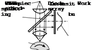
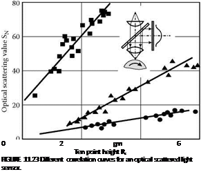
For the determination of macro — and microgeometrical quantities, a different optical system has to be applied. The basis of a scattered light sensor for the measurement of both roughness and waviness is the angular deflection of nearly normal incident rays. The setup of a scattered light sensor is shown in Figure 11.22 (bottom left). A beam-splitting mirror guides the reflected light to an array of diodes. A commercially available system was introduced in the 1980s [Brodtmann, Gast, and Thurn 1984] and used in a wide range of tests. The optical roughness measurement quantity of this system is called scattering value, SN, and is deduced from the intensity distribution. In different tests, the scattered light sensor was directly mounted in the working space of the grinding machine to measure the workpiece roughness. A compressed-air barrier protected the optical system. In all investigations, they tried to establish a correlation between optical and stylus roughness measurements.
It is possible to obtain a close relationship while grinding or honing with constant process parameters [von See 1989, Konig and Klumpen 1993] (Figure 11.23). This restriction is indispensable because a change of input variables like dressing conditions or tool specification may lead to workpieces with the same stylus roughness values, Ra or Rz, but different optical scattering values, SN. If a quantitative roughness characterization referring to stylus values is demanded, a timeconsuming calibration will always be necessary. As shown in Figure 11.23, the measuring direction has to be clearly defined to achieve the desired correlation. A second limitation is seen in the sensitivity of the system. The scattered light sensor is able to determine differences in high-quality surfaces, but for roughness states of ten-point height Rz > 5.0 pm, the scattering value, SN, is reaching its saturation with a decreasing accuracy already starting at Rz = 3.0 pm [von See 1989]. Thus, some relevant grinding or honing operations cannot be supervised by this sensor system.
■ OD axial grinding
 (steel)
optical measurement perpendicular to the grinding direction
A ID honing (cast iron) optical measurement parallel to the honing direction
• OD plunge grinding (case hardened steel) optical measurement parallel to the grinding direction
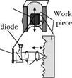
A different optical sensor is based on a laser diode [Westkamper et al. 1992] (Figure 11.22, top middle). The sensor is equipped with a gallium-arsenide diode, which is commonly used in a CD player. With a lens system, the beam is focused on the surface and the reflected light is registered on an array of four photo diodes. This system can be used as an autofocus system; with the signal from the four diodes the focus-lens is moved until the best position for minimum diameter is reached. The correlation of the obtained optical average roughness, Ra, opt, to the stylus reference measurement is shown in Figure 11.24 (left).
 |
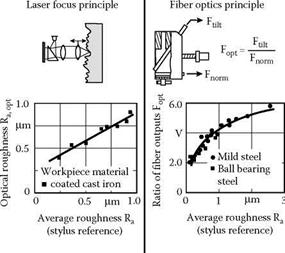 |
An almost linear dependence of the two different roughness quantities could be found, but this is much too slow to use the system for any in-process measurement. By using the focus-error signal of the four diodes without moving the lens, it is possible to increase the measurement speed significantly. Another optical approach for in-process roughness measurement is based on the use of optical fiber sensors [Inasaki 1985a]. The workpiece surface is illuminated through fiber optics and the intensity
of the reflected light is detected and evaluated (Figure 11.24, middle). The latter setup was chosen to increase the sensitivity of the sensor system. The photo sensor in normal direction will register less intensity, whereas the inclined photo sensor will detect more intensity with larger light scattering due to increased roughness. The ratio of both photo sensors is related to roughness changes. A second advantage of the setup with two fiber optics despite the increased sensitivity is the achieved independence of the workpiece material. Coolant is flowing around the whole sensor head to make measurement possible during grinding. It is essential to keep the coolant as clean as possible during operation because the reflection conditions are definitely influenced by the filtering state of the fluid. This is the major drawback of the sensor system because the coolant quality is not likely to be stable in production. Besides these mentioned systems some other optical techniques for online measurement of surface topography have been proposed, for example, speckle patterns. Although the measurement speed may allow installing these systems in the production line surrounding, it is not realistic to use it as a sensor in the machine tool working space.
In summary, because of all the problems related to coolant supply, it must be stated that these conditions do not allow using optical systems during grinding as reliable and robust industrial sensors. Only optical sensor applications measuring in interruptions of coolant supply either in the working space of the machine tool or in the direct surrounding have gained importance in industrial production.
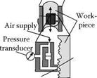
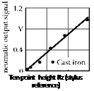
In addition to optical sensors, two other principles are used for noncontact workpiece characterization. A pneumatic sensor, as shown in Figure 11.22 (top right), was designed and used for the measurement of cylinder surfaces. The measurement is based on the already-mentioned nozzle — bounce plate principle. A correlation to stylus measurements is possible (Figure 11.24, right). Main advantages of this system are the small size, the robustness against impurities and coolant, and the fact that an area and not a trace is evaluated. So, on principle, any movement of the sensor during measurement is not necessary.
The last system to be introduced as a noncontact workpiece sensor is based on an inductive sensor. The sensor is used in gear grinding machines to identify the exact position of tooth and tooth slot at the circumference of the premachined and usually heat-treated gear (Figure 11.22, bottom right). The gear is rotating at high speed and the obtained signal is evaluated in the control unit of the grinding machine. This signal is used to index the gear in relation to the grinding wheel to define its precise position [Karpuschewski 2001].