
The best way to investigate the influence of any cutting or grinding process on the physical properties of the machined workpiece would be to directly measure on the generated surface. Until now only very few sensors are available to meet this demand. Two techniques are explained that have the highest potential for this purpose.
The principle of eddy-current measurement for crack detection is based on the fact that cracks at the workpiece surface will disturb the eddy-current lines, which are in the measuring area of a coil with alternating-current excitation. The feedback to the exciting field leads to changes of the impedance for coils with only one winding, respectively, to a change of the signal voltage for sensors with two separated primary and secondary windings. All kinds of conductive materials can be tested. The penetration depth is determined by the excitation frequency. Conductivity, as well as permeability of the workpiece, can be investigated. In grinding, an eddy-current sensor was introduced to monitor the occurrence of cracks.
In Figure 11.19 (left), the setup for this eddy-current-based measurement is shown, and is used for the determination of cracks generated during profile surface grinding of turbine blade roots [Lange 1996]. Figure 11.19 (right) shows the result of such a measurement. The crack was investigated afterward with the aid of a scanning electron microscope and had a width of 2 pm.
The eddy-current sensor could clearly determine this crack with a contact measurement. This size has to be regarded as the minimum resolution of the sensor. In any case, the sensor must be positioned in a perpendicular direction to the surface because any tilting is reducing the sensitivity. Thus, an additional shift option was implemented in the moving bridge. The results prove the suitability of eddy-current sensors for crack detection on turbine blade materials. Although the measurement speed was smaller than the grinding table speed, a check in the grinding machine may still be acceptable because of the high safety demand on these workpieces.
The second possibility to detect changes of the physical properties on machined surfaces of ferrous materials is based on micromagnetic techniques. Residual stresses, hardness values, and the structure in subsurface layers influence the magnetic domains of ferromagnetic materials. Any magnetization change can be measured with the so-called Barkhausen noise. The existence of compressive stress in ferromagnetic materials reduces the intensity of the Barkhausen noise whereas tensile stresses will increase the signal [Karpuschewski 1995]. In addition to these stress-sensitive
properties, the hardness and structure state of the workpiece also influence the Barkhausen noise. To separate the different material characteristics of a ground workpiece, different quantities deduced from the Barkhausen noise signal must be taken into consideration. The most important quantities deduced from the signal are the maximum amplitude of the Barkhausen noise, Mmax, and the coercivity, HcM. In any case, the measurement time is very short and amounts to only a few seconds, which is one of the major advantages of this technique. This so-called two-parameter micromagnetic set-up was further improved by adding modules for the measurement of the incremental permeability, the harmonics of the exciting field, and eddy-currents [Regent 1999]. The major aim of this multiparameter system was to further separate the influence of the initial material properties from the changes due to machining operations.
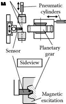
A detailed investigation of the potential of the two-parameter micromagnetic approach was employed to characterize surface integrity states of workpieces with different heat treatments [Karpuschewski 1995]. Afterward, this technique was transferred to practical application. Figure 11.20 (left) shows the results of a large industrial test on planetary gears ground with electroplated CBN grinding wheels [Regent 1999]. It is essential to adapt the sensor geometry to the geometrical situation on the workpiece. In this case, the critical area to be tested was on the tooth flanks, thus the sensor had to be adapted to the module of the gear. In Figure 11.20 (right), the results over the lifetime of an electroplated wheel are shown. The Barkhausen noise amplitude is corrected to consider slight changes of the excitation field. It can be seen that all gears where grinding burn was identified by nital etching were also recognized with the micromagnetic setup. However, gears with high Mmax, corr. values appear, which do not show any damage in nital etching. A possible explanation for this deviation is the different penetration depth of the methods. Nital etching gives only information about the very top layer of the workpiece. Any subsurface damage cannot be registered. Micromagnetic measurements can also reveal that damage depending on the frequency range.
 |
 |
|
The major challenge is to exactly identify the grinding burn limit. It has to be mentioned further that the measuring time required to scan all flanks of one gear is significantly higher than the
FIGURE 11.20 Micromagnetic surface integrity characterization of ground planetary gears.
 |
|
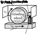
FIGURE 11.21 Micromagnetic in-process measurement of surface integrity during grinding.
grinding time. With intelligent strategies or increased number of sensors in parallel use, this time can be shortened for a suitable random testing. A total automated measurement is possible. Thus, the very inaccurate and environmentally hazardous etching can be replaced by this technology [Karpuschewski 2001].
Furthermore, in the laboratory, the first tests for in-process measurements of surface integrity changes based on this micromagnetic sensing were conducted for outer diameter and surface grinding [Tonshoff et al. 1998, Regent 1999]. In Figure 11.21, the first results of this approach during surface grinding of steel are presented. The sensor with integrated excitation is moving on the surface behind the grinding wheel at the chosen table speed of 8 m/min. Permanent contact is assured by spring loading. The X-ray measurement is done on one point of the ground surface, and the micromagnetic result represents the average over the whole workpiece length. The deviations in the area of compressive residual stresses and low-tensile residual stresses are less than 100 MPa, and only in areas of significant damage with tensile stresses higher than 200 MPa do the deviations increase. This can be explained by the occurrence of cracks after grinding due to the high thermal load on the workpiece.
Although further investigations on the wear resistance of the sensor head, on long-term coolant influence, maximum workpiece speed, geometrical restrictions, and other parameters have to be conducted, this sensor seems to offer the possibility of in-process workpiece surface integrity measurement for the first time.