
The loading of a grinding wheel with conductive metallic particles is a special type of microgeometrical wear that can be detected using sensors based on inductive phenomena. The sensor consists of a high permeability core and a winding. It is positioned a short distance from the surface. The metallic particles generate a change of impedance, which can be further processed to determine the state of wheel loading. Also, a conventional magnetic tape recorder head may be used to detect the presence and relative size of ferrous particles in the surface layer of a grinding wheel. Due to the fact that only this special type of wear in grinding of metallic materials can be detected, these sensors did not reach practical application.
Grinding

![]()

![]()
 wheel Sensor housing
with defined apertures for laser light and compressed air for protection
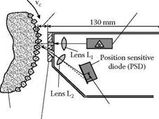
FIGURE 11.15 Measurement principle of a laser triangulation system.
The limitations of all techniques introduced so far drive attention toward optical methods. Optical methods are promising because of their frequency range and independence of the surface material. A scattered light sensor was used to determine the reflected light from the grinding wheel surface by using CCD arrays. Gotou and Touge [1996] adopted the principle with a silicon diode as a receiver and using a laser source. Grinding wheels in wet-type grinding at 30 m/s could be measured. It was stated that the wear flat areas are registered by the output signal and that these areas change during grinding.
The optical method with the highest technical level so far is based on laser triangulation. Figure 11.15 shows the basic elements, which are a laser diode with 40-mW continuous wave (c. w.) power and a position-sensitive detector (PSD) with amplifier and two lenses [Tonshoff, Karpuschewski, and Werner 1993]. The laser diode emits monochromatic laser light of 790-nm wavelength focused by lens, L1, on the grinding wheel surface. The scattered reflected light is collected by lens, L2, and focused on the PSD. If the distance to the sensor changes, the position of the reflected and focused light on the PSD also changes. The sensor is mounted to a two-axes stepper drive unit to be moved in normal direction to the grinding wheel surface and in axial direction to make measurements on different traces on the grinding wheel circumference. This sensor system was intensively tested in laboratory environment and in industrial application. For the determination of macrogeometrical quantities such as radial runout, no practical limitations exist. The maximum surface speed may even exceed 300 m/s.
Figure 11.16 shows the result of an investigation in outer diameter plunge grinding of ball bearing steel with a corundum grinding wheel. In dependence of three different material removal rates, the change of the radial runout as function of the material removal at 30 m/s is documented. For the smallest material removal rate, no change is detectable from the initial value after dressing. However, for increasing material removal rates of Q w = 1,0 mm3/mm/s, respectively, 2,0 mm3/mm/s, the radial runout is rising after a specific material removal. In the latter cases, the increasing radial runout leads to chatter vibrations with visible marks on the workpiece surface. Obviously the system is capable of detecting significant macrogeometric changes due to wear of the grinding wheel.
For microgeometrical measurements, the investigations have revealed that the maximum speed of the grinding wheel should not exceed 20 m/s based on hardware and software limitations. This means that, for most applications, the grinding wheel has to be decelerated for the measurement. This major drawback is limiting the practical field of application. For conventional abrasives with relatively short dressing intervals, an economic use of this type of microgeometrical monitoring is
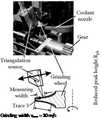
not possible if the wheel has to be decelerated. The most interesting application for this sensor is seen in the monitoring of superabrasives, especially CBN-grinding wheels. This sensor system was intensively tested during profile grinding of gears with an electroplated CBN-grinding wheel [Regent 1999]. The measurement was done on the involute profile of the grinding wheel on 10 traces during the workpiece changing time at a measurement speed of vmea = 10 m/s.
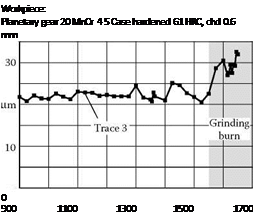
Figure 11.17 (left) shows the setup of the investigation. On the right-hand side, a result of this sensor application is presented. The measured quantity is the reduced peak height, Rpk, deduced from the bearing ratio curve, which can be used to describe the change of the grinding wheel topography at the grain tips.
As shown, the change in Trace 3 can be clearly correlated with the occurrence of grinding burn, which was confirmed by nital etching and succeeding metallographical and X-ray inspection.
 Grinding wheel:
CBN B 126 electroplated ds = 120 mm Grinding conditions: vc = 42 m/s
Q’w (roughing) = 5 mm3/mm/s
Although this result is very promising, some problems have to be taken into consideration. Measurements, as well as simulations, have revealed that it is not possible to correlate the sensor roughness results definitely to a specific wear pattern. In real applications, there are always several types of wear, for example, grain flattening and loading, that cannot be separated by the measuring quantities.
The examples shown for grinding wheel sensors reveal that the majority of systems are related to macrogeometrical features. Many attempts have been made to establish optical systems for the measurement of microgeometrical quantities. The overall limitation for these techniques will always be the hostile conditions in the working space of a grinding machine with coolant and process residues in direct contact with the object to be measured. In many cases it is thus preferable to directly measure the manufactured workpiece.