The ultimate goal of research is to develop practical means for suppressing vibrations. Based on understanding of the chatter principle, a number of practical methods have been proposed. The methods can be categorized into one of three strategies shown in Figure 8.16:
• Modification of the grinding conditions,
• Increase of the dynamic stiffness of the mechanical system, and
•
 |
Disturbing the regenerative effect.
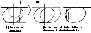 |
FIGURE 8.17 Strategies for suppressing regenerative chatter.
Figure 8.16 represents a block diagram of the simplified dynamic grinding system that consists of the grinding stiffness, the mechanical system, and the regenerative feedback loop. The block diagram is valid for workpiece regenerative chatter.
A stability analysis based on the dynamic model depicted in Figure 8.16 can be achieved as shown in Figure 8.17. The dynamic compliances of the mechanical system are represented by vector loci on the complex planes, while straight lines parallel to the imaginary axes represent the material removal process. Instability occurs when both lines have intersections. Based on those representations, methods for suppressing the regenerative chatter vibration can be further categorized as follows:
1. Modification of grinding conditions (Figure 8.17a)
2. Increase of the dynamic stiffness of the mechanical system
a. Increase of the static stiffness (Figure 8.17b)
b. Decrease of the orientation factor (Figure 8.17b)
c. Increase of the damping (Figure 8.17c)
3. Shifting the vector locus of the dynamic compliance to positive real part (Figure 8.17d)
4. Disturbing the regenerative effect (Figure 8.17e)
With respect to Method 1, decrease of the grinding stiffness is the most straightforward because it results in shifting the line parallel to the imaginary axis to the left and, consequently, the intersections of both lines can be avoided. Decrease of the grinding width and the workpiece speed meets this requirement (Figure 8.11).
Increase of the static stiffness or decrease of the orientation factor is effective for shrinking the vector loci and consequently for improving the dynamic performance of the grinding machines (Method 2.a and Method 2.b). Figure 8.18 shows an influence of the orientation factor on the stability [Inasaki et al. 1974]. In this series of grinding tests, the cross section of the workpiece center was modified from circular to rectangular and its orientation angle was changed. Interestingly, the critical limit in terms of grinding width changes depending on the orientation angle of the workpiece center. Influence of the static stiffness and the orientation factor on the stability is significant; therefore, it is worthwhile to take this effect into account at the design stage of a grinding machine.
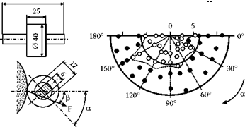 |
FIGURE 8.18 Influence of the orientation factor on chatter stability.
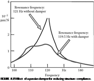 |
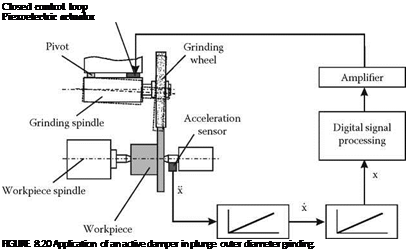
Another strategy for improving the dynamic performance of the mechanical system is to increase the damping by adding some kinds of dampers. Methods are divided into two kinds: application of passive [Tonshoff and Grosebruch 1988] and active dampers. Figure 8.19 shows an example of passive damper application [Hong, Nakano, and Kato 1990]. In this case, the damper is attached to the wheel head of the cylindrical grinding machine. Passive dampers are effective only when they are optimally tuned to the main mechanical system and the vibration characteristic of the mechanical system does not change significantly during the operation. However, application of active dampers is more flexible and can cope with a change in the vibration characteristics of the mechanical system. Figure 8.20 shows an example of the active damper application [Weck and Brecher 2001].
 |
Shifting the vector locus to the right on the complex plane, Method 3 can be achieved by adding a spring element between the workpiece and the grinding wheel. It is essential here to add only the spring element without any additional mass to the system. The resultant vector locus after the attachment of the spring element ka is
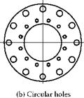
This idea for suppressing the chatter vibration can be realized to some extent by decreasing the contact stiffness of the grinding wheel [Sexton and Stone 1981]. Figure 8.21 shows an example of the grinding wheel modified to meet the idea.
 |
|
 |
 |
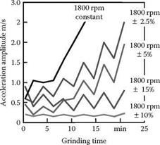
A practical method for suppressing self-excited vibration is to intentionally disturb the phase shift between the inner and the outer modulation (Method 4). This idea can be put into practice by periodically varying the rotational speed of either the workpiece or the grinding wheel. The former method is effective for suppressing workpiece regenerative chatter [Inasaki 1977b] while the latter one is effective for suppressing grinding wheel regenerative chatter [Hoshi et al. 1986]. Figure 8.22
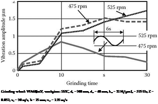 |
FIGURE 8.22 Chatter suppression by varying workpiece rotational speed.
and Figure 8.23 show the effect of varying the workpiece rotational speed and the grinding wheel rotational speed, respectively. The methods introduced here are effective and practical; however, the applications are restricted to rough grinding because varying the rotational speed may have some adverse effect on the surface quality of the ground parts.
 |
 |
From the theoretical point of view, it can be said that the mechanism of self-excited chatter vibration in grinding has been made clear. Self-excited chatter is a result of regenerative effects on both the workpiece and the grinding wheel surfaces. A full description of chatter is, however, complex. This is mainly due to the difficulty of identifying the required dynamic characteristics of the process, of the grinding machine, and of the grinding wheel. In addition, those characteristics are likely to change during the grinding process. Taking those difficulties into account, it is considered that a
sophisticated chatter suppression system is required that consists of monitoring and control of chatter to meet the requirement for precision grinding processes. Advanced sensors and actuators available today are generally expected to make the achievement of chatter control possible. For the roughing process, however, periodical change of the grinding wheel rotational speed as well as workpiece rotational speed appears to be a practical solution. It is also desirable to give a higher compliance to the grinding wheel surface. With respect to grinding machine design, it is essential to increase stiffness and damping in order to achieve high dynamic stability.
